DS3510TR データシートの表示(PDF) - Maxim Integrated
部品番号
コンポーネント説明
メーカー
DS3510TR Datasheet PDF : 17 Pages
| |||
I2C Gamma and VCOM Buffer with EEPROM
Table 3. DAC Voltage/Data Relationship for Selected Codes
SETTING
(HEX)
00h
01h
02h
03h
0Fh
3Fh
7Fh
FDh
FEh
FFh
VCOM OUTPUT VOLTAGE
VRL
VRL + (1/255) x (VRH - VRL)
VRL + (2/255) x (VRH - VRL)
VRL + (3/255) x (VRH - VRL)
VRL + (15/255) x (VRH - VRL)
VRL + (63/255) x (VRH - VRL)
VRL + (127/255) x (VRH - VRL)
VRL + (253/255) x (VRH - VRL)
VRL + (254/255) x (VRH - VRL)
VRH
GM1–GM5 OUTPUT VOLTAGE
GLL
GLL + (1/256) x (GLM - GLL)
GLL + (2/256) x (GLM - GLL)
GLL + (3/256) x (GLM - GLL)
GLL + (15/256) x (GLM - GLL)
GLL + (63/256) x (GLM - GLL)
GLL + (127/256) x (GLM - GLL)
GLL + (253/256) x (GLM - GLL)
GLL + (254/256) x (GLM - GLL)
GLL + (255/256) x (GLM - GLL)
GM6–GM10 OUTPUT VOLTAGE
GHM + (255/256) x (GHH - GHM)
GHM + (254/256) x (GHH - GHM)
GHM + (253/256) x (GHH - GHM)
GHM + (252/256) x (GHH - GHM)
GHM + (240/256) x (GHH - GHM)
GHM + (192/256) x (GHH - GHM)
GHM + (128/256) x (GHH - GHM)
GHM + (2/256) x (GHH - GHM)
GHM + (1/256) x (GHH - GHM)
GHM
like the other modes, the LD pin determines when the
DACs get updated. If the LD signal is high, Latch B is
flow-through and the DAC is updated immediately. If
LD is low, Latch B will be loaded from Latch A after a
low-to-high transition on the LD pin. This latter method
allows the timing of the DAC update to be controlled by
an external signal pulse.
VCOM/Gamma Channel Outputs
As illustrated in the Block Diagram, the VCOM and
gamma channel outputs are equivalent to an 8-bit digi-
tal potentiometer (DAC) with a buffered output. The
VCOM channel’s digital potentiometer is comprised of
255 equal resistive elements. The relationship between
output voltage and DAC setting is illustrated in Table 3.
Unlike the gamma channels, the VCOM channel is
capable of outputting a range of voltages including
both references (VRH and VRL). Each of the gamma
channel digital potentiometers, on the other hand, are
comprised of 256 equal resistive elements. The extra
resistive element prohibits one of the rails from being
reached. In particular, gamma channel outputs
GM1–GM5 can span from (and including) GLL to 1 LSB
away from GLM. Likewise, gamma channel outputs
GM6–GM10 span from (and including) GHM to 1 LSB
away from GHH. The relationship between output volt-
age and DAC setting for the gamma channels is also
illustrated in Table 3.
Standby Mode
Standby mode (not to be confused with the three
DS3510 operating modes) can be used to minimize
current consumption. Standby mode is entered by set-
ting the standby bit, which is the LSB of register 51h.
The VCOM and gamma outputs are placed in a high-
impedance state. Current drawn from the VDD supply in
this state is specified as IDDQ.
The DS3510 continues to respond to I2C commands,
and thus draws some current from VCC when I2C activi-
ty is occurring. When the I2C interface is inactive, cur-
rent drawn from the VCC supply is specified as ICCQ.
Thermal Shutdown
As a safety feature, the DS3510 goes into a thermal
shutdown state if the junction temperature ever reaches
or exceeds +150°C. In this state, the VCOM buffer is
disabled (output goes high impedance) until the junc-
tion temperature falls below +150°C.
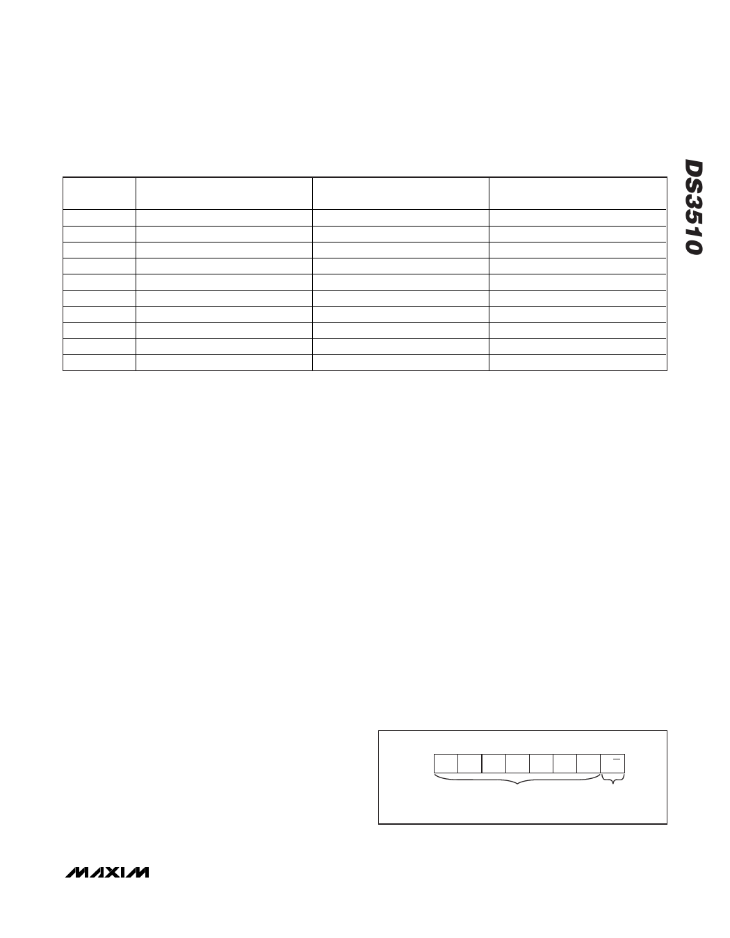
Slave Address Byte and Address Pin
The slave address byte consists of a 7-bit slave
address plus a R/W bit (see Figure 5). The DS3510’s
slave address is determined by the state of the A0 pin.
This pin allows up to two devices to reside on the same
I2C bus. Connecting A0 to GND results in a 0 in the cor-
responding bit position in the slave address.
Conversely, connecting A0 to VCC results in a 1 in the
corresponding bit position. For example, the DS3510’s
slave address byte is C0h when A0 is grounded. I2C
communication is described in detail in the I2C Serial
Interface Description section.
MSB
LSB
1 1 0 0 0 0 A0 R/W
SLAVE ADDRESS*
*THE SLAVE ADDRESS IS DETERMINED BY ADDRESS PIN A0.
Figure 5. DS3510 Slave Address Byte
______________________________________________________________________________________ 11
Share Link: 