DS3510TT データシートの表示(PDF) - Maxim Integrated
部品番号
コンポーネント説明
メーカー
DS3510TT Datasheet PDF : 17 Pages
| |||
I2C Gamma and VCOM Buffer with EEPROM
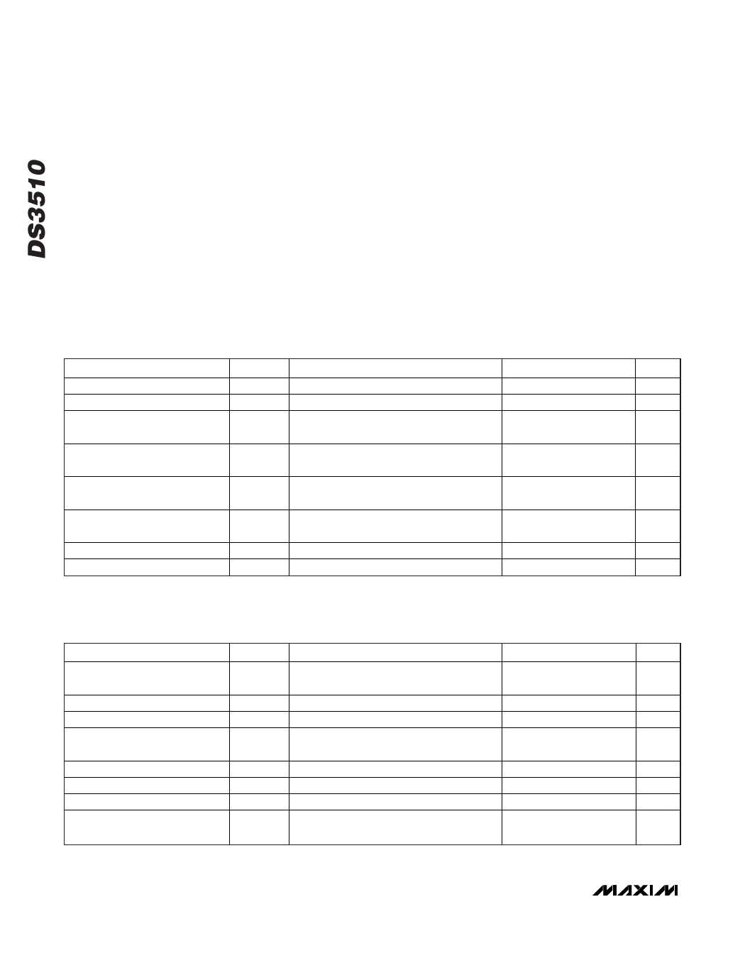
ABSOLUTE MAXIMUM RATINGS
Voltage on VDD Relative to GND ............................-0.5V to +16V
Voltage on VRL, VRH, GHH, GHM, GLM, GLL
Relative to GND........-0.5V to (VDD + 0.5V), not to exceed 16V
Voltage on VCC Relative to GND ..............................-0.5V to +6V
Voltage on SDA, SCL, A0, LD, S0,
S1 Relative to GND ....-0.5V to (VCC + 0.5V), not to exceed 6V
Junction Temperature ......................................................+125°C
Operating Temperature Range ...........................-45°C to +95°C
Programming Temperature Range .........................0°C to +70°C
Storage Temperature Range .............................-55°C to +125°C
Soldering Temperature...............Refer to IPC/JEDEC J-STD-020
Specification.
Stresses beyond those listed under “Absolute Maximum Ratings” may cause permanent damage to the device. These are stress ratings only, and functional
operation of the device at these or any other conditions beyond those indicated in the operational sections of the specifications is not implied. Exposure to
absolute maximum rating conditions for extended periods may affect device reliability.
RECOMMENDED OPERATING CONDITIONS
(TA = -45°C to +95°C.)
PARAMETER
Digital Supply Voltage
Analog Supply Voltage
SYMBOL
VCC
VDD
(Note 1)
(Note 1)
CONDITIONS
VRH, VRL Voltage
VVCOM Applies to VCOM output
GHH, GHM, GLM, GLL Voltage
Input Logic 1
(SCL, SDA, A0, S0, S1, LD)
Input Logic 0
(SCL, SDA, A0, S0, S1, LD)
VCOM Load Capacitor
VCAP Compensation Capacitor
VGM1–10 Applies to GM1–GM10
VIH
VIL
CD
CCOMP
MIN
+2.7
+9.0
TYP
MAX
+5.5
+15.0
UNITS
V
V
+2.0
VDD - 2.0
V
GND +
0.2
0.7 x
VCC
VDD - 0.2
V
VCC
V
+ 0.3
-0.3
0.3 x VCC V
1
µF
0.1
µF
INPUT ELECTRICAL CHARACTERISTICS
(VCC = +2.7V to +5.5V, TA = -45°C to +95°C, unless otherwise noted.)
PARAMETER
SYMBOL
CONDITIONS
Input Leakage (SDA, SCL, S0,
S1, LD)
IL
Input Leakage (A0)
VDD Supply Current
VCC Supply Current, Nonvolatile
Read or Write
IL:A0
IDD
ICC
(Notes 2, 3)
(Note 4)
VCC Standby Supply Current
VDD Standby Supply Current
I/O Capacitance (SDA, SCL, A0)
End-to-End Resistance
(VRH to VRL)
ICCQ
IDDQ
CI/O
(Note 5)
(Note 6)
(Note 7)
RTOTAL
MIN TYP MAX UNITS
-1
+1
µA
2
mA
6.7 15.0 mA
0.2
1.0
mA
1.8
10.0
µA
2
4
mA
5
10
pF
16
k
2 _______________________________________________________________________________________
Share Link: 