APT60M75JFLL „Éá„Éľ„āŅ„ā∑„Éľ„Éą„ĀģŤ°®Á§ļÔľąPDFÔľČ - Advanced Power Technology
ťÉ®ŚďĀÁē™ŚŹ∑
„ā≥„É≥„ÉĚ„Éľ„Éć„É≥„ÉąŤ™¨śėé
„É°„Éľ„āę„Éľ
APT60M75JFLL Datasheet PDF : 5 Pages
| |||
DYNAMIC CHARACTERISTICS
Symbol Characteristic
Test Conditions
Ciss
Coss
Crss
Qg
Qgs
Qgd
td(on)
tr
td(off)
tf
Eon
Eoff
Eon
Eoff
Input Capacitance
Output Capacitance
Reverse Transfer Capacitance
Total Gate Charge 3
Gate-Source Charge
Gate-Drain ("Miller ") Charge
Turn-on Delay Time
Rise Time
Turn-off Delay Time
Fall Time
Turn-on Switching Energy 6
Turn-off Switching Energy
Turn-on Switching Energy 6
Turn-off Switching Energy
VGS = 0V
VDS = 25V
f = 1 MHz
VGS = 10V
VDD = 300V
ID = 58A @ 25¬įC
RESISTIVE SWITCHING
VGS = 15V
VDD = 300V
ID = 58A @ 25¬įC
RG = 0.6‚Ą¶
INDUCTIVE SWITCHING @ 25¬įC
VDD = 400V, VGS = 15V
ID = 58A, RG = 5‚Ą¶
INDUCTIVE SWITCHING @ 125¬įC
VDD = 400V VGS = 15V
ID = 58A, RG = 5‚Ą¶
SOURCE-DRAIN DIODE RATINGS AND CHARACTERISTICS
Symbol Characteristic / Test Conditions
IS
Continuous Source Current (Body Diode)
ISM Pulsed Source Current 1 (Body Diode)
VSD Diode Forward Voltage 2 (VGS = 0V, IS = -58A)
dv/dt Peak Diode Recovery dv/dt 5
Reverse Recovery Time
trr
(IS = -58A, di/dt = 100A/¬Ķs)
Reverse Recovery Charge
Qrr
(IS = -58A, di/dt = 100A/¬Ķs)
Peak Recovery Current
IRRM (IS = -58A, di/dt = 100A/¬Ķs)
Tj = 25¬įC
Tj = 125¬įC
Tj = 25¬įC
Tj = 125¬įC
Tj = 25¬įC
Tj = 125¬įC
THERMAL CHARACTERISTICS
Symbol Characteristic
RőłJC
RőłJA
Junction to Case
Junction to Ambient
MIN
MIN
MIN
APT60M75JFLL
TYP MAX UNIT
8930
1130
pF
50
195
48
nC
100
23
15
ns
55
10
1205
1385
¬ĶJ
1865
1550
TYP MAX UNIT
58 Amps
232
1.3 Volts
15 V/ns
300
ns
600
2.6
¬ĶC
10
17
Amps
34
TYP MAX UNIT
0.21
40
¬įC/W
1 Repetitive Rating: Pulse width limited by maximum junction
temperature
2 Pulse Test: Pulse width < 380 ¬Ķs, Duty Cycle < 2%
3 See MIL-STD-750 Method 3471
4 Starting Tj = +25¬įC, L = 1.90mH, RG = 25‚Ą¶, Peak IL = 58A
5 dv/dt numbers reflect the limitations of the test circuit rather than the
device itself. IS ‚ȧ -ID58A di/dt ‚ȧ 700A/¬Ķs VR ‚ȧ 600V TJ ‚ȧ 150¬įC
6 Eon includes diode reverse recovery. See figures 18, 20.
APT Reserves the right to change, without notice, the specifications and inforation contained herein.
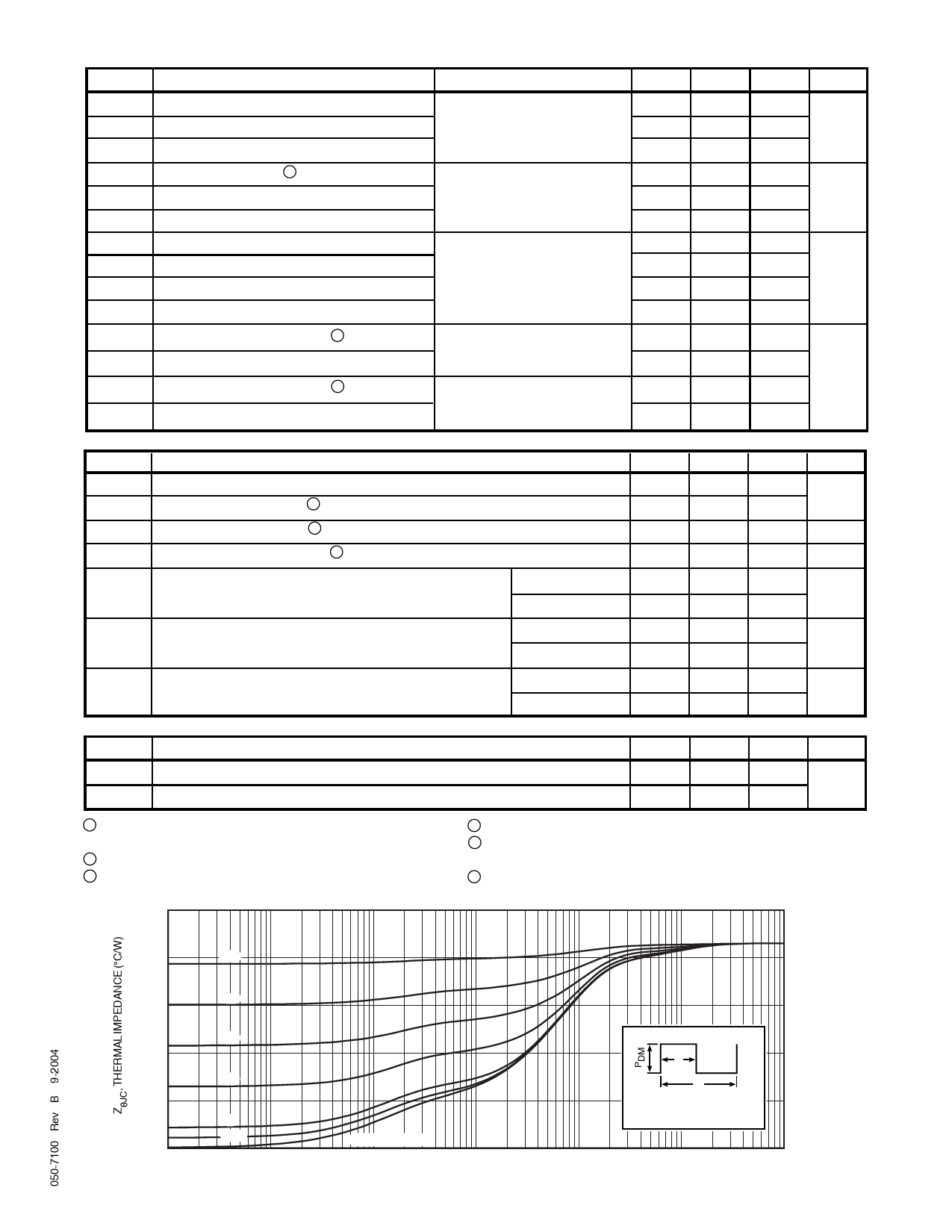
0.25
0.20
0.9
0.15
0.7
0.10
0.05
0 10-5
0.5
Note:
t1
0.3
t2
Duty Factor D = t1/t2
0.1
Peak TJ = PDM x ZőłJC + TC
0.05
SINGLE PULSE
10-4
10-3
10-2
10-1
1.0
10
RECTANGULAR PULSE DURATION (SECONDS)
FIGURE 1, MAXIMUM EFFECTIVE TRANSIENT THERMAL IMPEDANCE, JUNCTION-TO-CASE vs PULSE DURATION
Share Link: 