KBPC3510W データシートの表示(PDF) - HY ELECTRONIC CORP.
部品番号
コンポーネント説明
メーカー
KBPC3510W Datasheet PDF : 2 Pages
| |||
SILICON BRIDGE RECTIFIERS
FEATURES
●Surge overload -240~500 Amperes peak
● Low forward voltage drop
● Mounting Position : Any
● Electrically isolated base -2000 Volts
● Materials used carries U/L recognition
KBPC10/15/25/35/50AW SERIES
REVERSE VOLTAGE - 50 to 1000Volts
FORWARD CURRENT - 10/15/25/35/50 Amperes
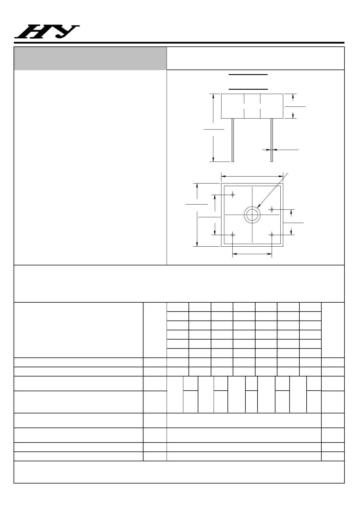
KBPC-W
1.200
(30.5)MIN
.442(11.23)
.424(10.77)
1.133(28.8)
1.114(28.3)
.042(1.07)
.038(0.97)
Hole for
No.8 screw
193"(4.9)diam
1.133(28.8)
1.114(28.3)
.732(18.6)
.693(17.6)
.469(11.9)
.429(10.9)
.732(18.6)
.693(17.6)
Dimensions in inches and (milimeters)
MAXIMUM RATINGS AND ELECTRICAL CHARACTERISTICS
Rating at 25℃ ambient temperature unless otherwise specified.
Resistive or inductive load 60Hz.
For capacitive load current by 20%
KBPC-W KBPC-W KBPC-W KBPC-W KBPC-W KBPC-W KBPC-W
10005 1001 1002 1004 1006 1008 1010
CHARACTERISTICS
15005
SYMBOL
25005
1501
2501
1502
2502
1504
2504
1506
2506
1508
2508
1510
2510
35005 3501 3502 3504 3506 3508 3510
50005 5001 5002 5004 5006 5008 5010
Maximum Recurrent Peak Reverse Voltage
VRRM
50
100
200
400
600
800
1000
Maximum RMS Bridge Input Voltage
Maximum Average Forward
Rectified Output Current @TC=55℃
Peak Forward Surge Current
8.3ms Single Half Sine-Wave
Super Imposed on Rated Load
Maximum Forward Voltage Drop Per Element
at 5.0/7.5/12.5/17.5/25.0A Peak
Maximum Reverse Current at Rate
DC Blocking Voltage Per Element @TJ=25℃
Operating Temperature Range
VRMS
I(AV)
IFSM
35
70
140
280
420
560
700
10
KBPC
10W
240
15
25
35
KBPC
KBPC
KBPC
15W
25W
35W
300
400
400
50
KBPC
50W
500
VF
1.1
IR
10
TJ
-55 to +125
Storage Temperature Range
TSTG
-55 to +150
UNIT
V
V
A
A
V
μA
℃
℃
~ 330 ~
Share Link: 