VS-MURB2020CT-1TRLP データシートの表示(PDF) - Vishay Semiconductors
部品番号
コンポーネント説明
メーカー
VS-MURB2020CT-1TRLP Datasheet PDF : 10 Pages
| |||
VS-MURB2020CTPbF, VS-MURB2020CT-1PbF
www.vishay.com
Vishay Semiconductors
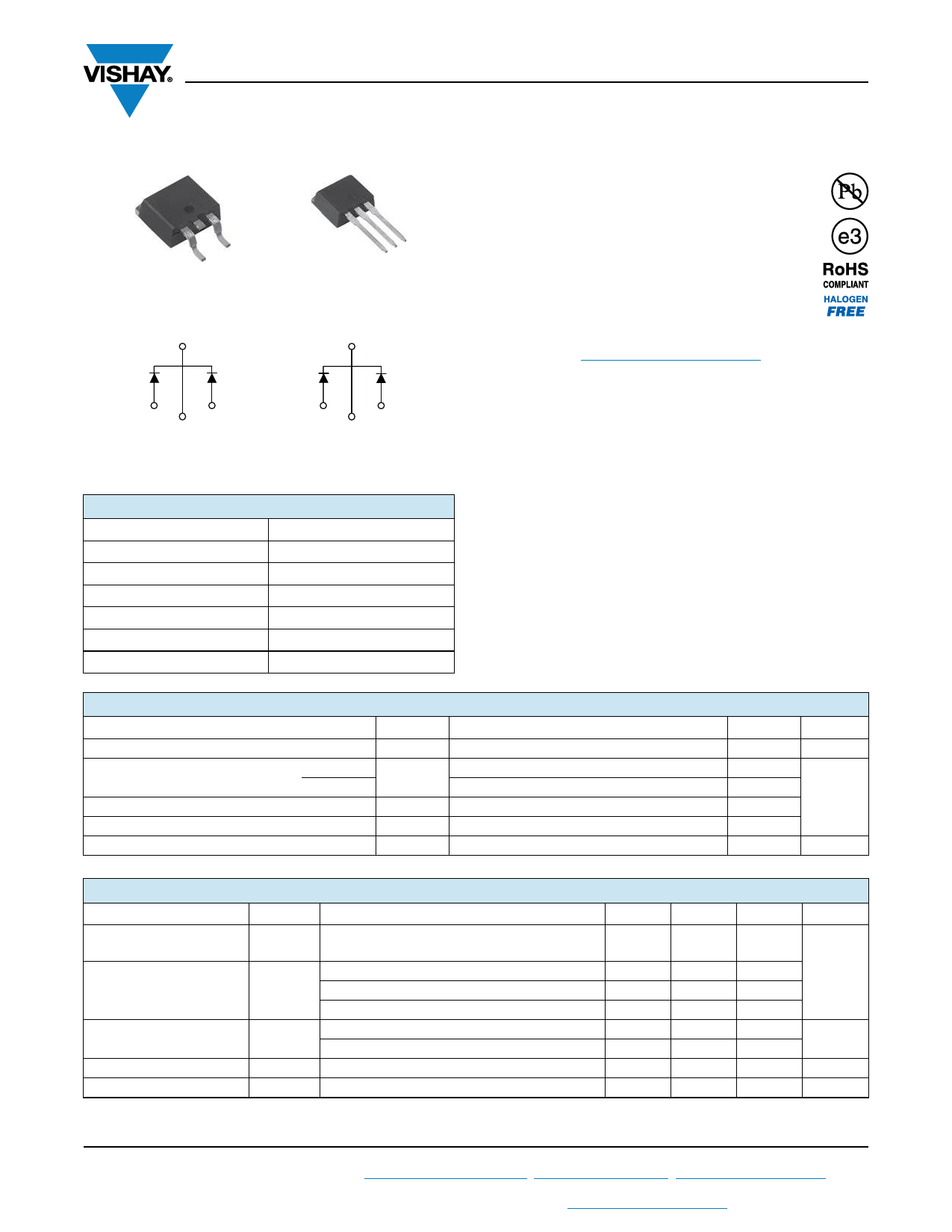
Ultrafast Rectifier, 2 x 10 A FRED Pt®
TO-263AB (D2PAK)
Base
common
cathode
2
TO-262AA
Base
common
cathode
2
FEATURES
• Ultrafast recovery time
• Low forward voltage drop
• Low leakage current
• 175 °C operating junction temperature
• Meets MSL level 1, per J-STD-020, LF maximum
peak of 260 °C
• AEC-Q101 qualified
• Material categorization: for definitions of compliance
please see www.vishay.com/doc?99912
12
3
Anode
Anode
1 Common 2
cathode
VS-MURB2020CTPbF
12
3
Anode
Anode
1 Common 2
cathode
VS-MURB2020CT-1PbF
PRODUCT SUMMARY
Package
TO-263AB (D2PAK), TO-262AA
IF(AV)
VR
VF at IF
trr
TJ max.
Diode variation
2 x 10 A
200 V
0.85 V
35 ns
175 °C
Common cathode
DESCRIPTION / APPLICATIONS
MUR.. series are the state of the art ultrafast recovery
rectifiers specifically designed with optimized performance
of forward voltage drop and ultrafast recovery time.ÔÄÝ
The planar structure and the platinum doped life time
control, guarantee the best overall performance,
ruggedness and reliability characteristics.ÔÄÝ
These devices are intended for use in the output rectification
stage of SMPS, UPS, DC/DC converters as well as
freewheeling diode in low voltage inverters and chopper
motor drives.ÔÄÝ
Their extremely optimized stored charge and low recovery
current minimize the switching losses and reduce over
dissipation in the switching element and snubbers.ÔÄÝ
ÔÄÝ
ÔÄÝ
ÔÄÝ
ÔÄÝ
ÔÄÝ
ÔÄÝ
ÔÄÝ
ABSOLUTE MAXIMUM RATINGS
PARAMETER
Peak repetitive reverse voltage
Average rectified forward current
per leg
total device
Non-repetitive peak surge current per leg
Peak repetitive forward current per leg
Operating junction and storage temperatures
SYMBOL
VRRM
IF(AV)
IFSM
IFM
TJ, TStg
TEST CONDITIONS
Rated VR, TC = 145 °C
Rated VR, square wave, 20 kHz, TC = 145 °C
MAX.
200
10
20
100
20
-65 to +175
UNITS
V
A
°C
ELECTRICAL SPECIFICATIONS (TJ = 25 °C unless otherwise specified)
PARAMETER
SYMBOL
TEST CONDITIONS
MIN.
Breakdown voltage,ÔÄÝ
blocking voltage
Forward voltage
Reverse leakage current
Junction capacitance
Series inductance
VBR,
VR
VF
IR
CT
LS
IR = 100 μA
200
IF = 8 A, TJ = 125 °C
-
IF = 16 A
-
IF = 16 A, TJ = 125 °C
-
VR = VR rated
-
TJ = 150 °C, VR = VR rated
-
VR = 200 V
-
Measured lead to lead 5 mm from package body
-
TYP.
-
-
-
-
-
-
55
8.0
MAX.
-
0.85
1.15
1.05
15
250
-
-
UNITS
V
μA
pF
nH
Revision: 10-Jul-15
1
Document Number: 94083
For technical questions within your region: DiodesAmericas@vishay.com, DiodesAsia@vishay.com, DiodesEurope@vishay.com
THIS DOCUMENT IS SUBJECT TO CHANGE WITHOUT NOTICE. THE PRODUCTS DESCRIBED HEREIN AND THIS DOCUMENT
ARE SUBJECT TO SPECIFIC DISCLAIMERS, SET FORTH AT www.vishay.com/doc?91000
Share Link: 