RF3330PCBA-41X データシートの表示(PDF) - RF Micro Devices
部品番号
コンポーネント説明
メーカー
RF3330PCBA-41X Datasheet PDF : 10 Pages
| |||
RF3330
offset needs to be applied to the signal generator. The formulas used to calculate this offset are given below in Equations 1
through 3. It should be noted that the unbalanced 1000Ω load is used, because all data in the datasheet is referenced to sin-
gle-ended operation. Using a spectrum analyzer probe, the actual offset measured was 7.5dB, and this is what is used for the
amplitude offset in the signal generator.
Mismatch Loss (ML)=-10*log(1-|ΓL|2)Eq. 1
ΓL =(Z-Z0)/(Z+Z0)Eq. 2
ML = -10 * log (1 - [(1000 -50) / (1000+50)]2) = 7.4 dB
Eq. 3
Output
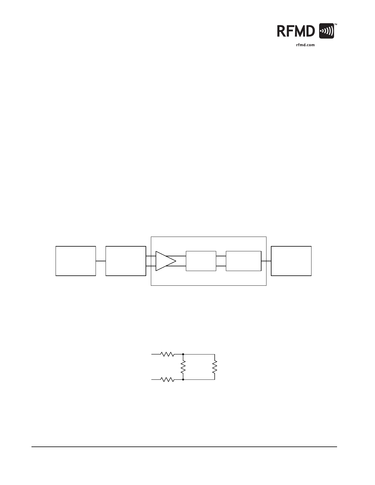
On the output, the losses due to the resistive matching pad must also be calibrated out of the setup. Because of the 1:1 trans-
former, the spectrum analyzer appears as a 50Ω resistor in parallel with this circuit (see Figure 2). Equation 4 illustrates the
calculation necessary to obtain the amount of loss due to this matching circuit. The balun also has an additional 0.5dB to
1.0dB of loss, which is added in to the overall output losses. This was verified with a spectrum analyzer probe. The offset used
in the test setup is 32.5dB on the spectrum analyzer.
Resistive Pad Loss=
20*log(25/(470+25+470))=-31.7dBEq. 4
Frequency =
1 MHz to
150 MHz
Frequency =
1 MHz to
150 MHz
Signal Generator
Mini-Circuits
ZMSCJ-2-1
Divider
Figure 1. RF3330 Test Setup
RF3330
Resistive
Match
1:1
Transformer
Frequency =
1 MHz to
150 MHz
3330410 Evaluation Board
Spectrum Analyzer
R4
470 Ω
R3
51 Ω
50 Ω
R2
470 Ω
Figure 2. Equivalent Output Circuit
8 of 10
7628 Thorndike Road, Greensboro, NC 27409-9421 · For sales or technical
support, contact RFMD at (+1) 336-678-5570 or sales-support@rfmd.com.
Rev A4 DS060908
Share Link: 