CMV1036 データシートの表示(PDF) - California Micro Devices Corp
部品番号
コンポーネント説明
メーカー
CMV1036 Datasheet PDF : 12 Pages
| |||
CALIFORNIA MICRO DEVICES
CMV1036
Applications Information
1. Input Common Mode Range and Output
Voltage Considerations
The CMV1036 is capable of accommodating an input
common mode voltage equal to one volt below the
positive rail and all the way to the negative rail. It is
also capable of output voltages equal to both power
supply rails. Voltages that exceed the supply voltages
will not cause phase inversion of the output, however,
ESD diode clamps are provided at the inputs that can
be damaged if static currents in excess of ±5mA are
allowed to flow in them. This can occur when the
magnitude of input voltage exceeds the rail by more
than 0.3 volt. To preclude damage, an applications
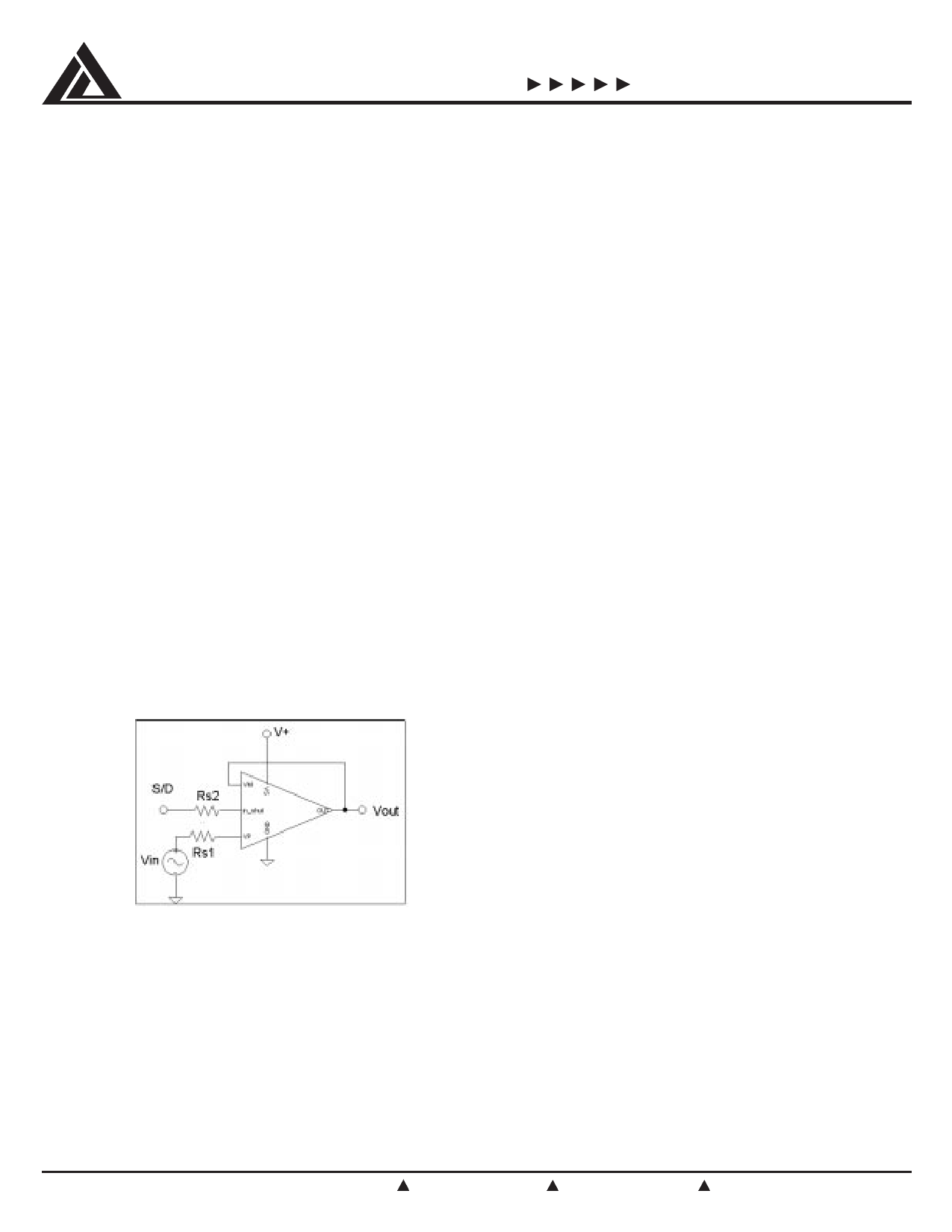
resistor, RS, in series with the input is recommended
as illustrated in Figure 1 whose value for RS is given
by:
VIN – (V+ + 0.3 V)
RS > —————————
5 mA
For V+ (or V–) equal to 2.2 volts and VIN equal to 10
volts,
R
S
should
be
chosen
for
a
value
of
2.5KΩ
or
greater.
The Shutdown pin also provides ESD clamp diodes
that will be damaged if the signal exceeds the rail by
0.3 volts and should also be limited to <5mA by
inserting the appropriate resistor between the input
signal or logic gate and the Shutdown input.
Obviously, the worst case from a power dissipation
point of view is when the output is shorted to either
ground in a single rail application or to the opposite
supply voltage in split rail applications. Since device
only draws 60µA supply current (100µA maximum), its
contribution to the junction temperature, TJ, is negli-
gible. As an example, let us analyze a situation in
which the CMV1036 is operated from a 5 volt supply
and ground, the output is “programmed” to positive
saturation, and the output pin is indefinitely shorted to
ground. In general:
PDISS = (V+ –VOUT)*IOUT + IS*V+
Where: PDISS = Power dissipated by the chip
V+ = Supply voltage
VOUT = The output voltage
IS = Supply Current
The contribution to power dissipation due to supply
current is 500µW and is indeed negligible as stated
above.
The primary contribution to power dissipation occurs in
the output stage. V+ – V would equal 5V– 0V = 5 V
OUT
while the short circuit current would be 25mA. The
power dissipation would be equal to 125mW.
T
J
=
T
A
+
θJA*
P
diss
Where: TA = The ambient temperature
θJA = The thermal impedance of the package
junction to ambient
The SOT23 exhibits a θJA equal to 325°C/W. Thus for
our example the junction rise would be about 41°C
which is clearly not a destructive situation even under
an ambient temperature of 85°C.
3. Input Impedance Considerations
Figure 1.
2. Output Current and Power Dissipation
Considerations
The CMV1036 is capable of sinking and sourcing
output currents in excess of 7mA (V+ = 2.2 volts) at
voltages very nearly equal to the rails. As such, it
does not have any internal short circuit protection
(which would in any event detract from its rail to rail
capability). Although the power dissipation and junction
temperature rise are small, a short analysis is worth
investigating.
The CMV1036 exhibits an input impedance typically in
excess of 1 Tera Ω (1 X 10¹² ohms) making it very
appropriate for applications involving high source
impedance such as photodiodes and high output
impedance transducers or long time constant integra-
tors. High source impedances usually dictate large
feedback resistors. But, the output capacitance of the
source in parallel with the input capacitance of the
CMV1036 (which is typically 3pF) create a parasitic
pole with the feedback resistor which erodes the
phase margin of the amplifier. The usual fix is to
bypass, RF, as shown in Figure 2 with a small capaci-
tor to cancel the input pole. The usual formula for
calculating CF always results in a value larger than that
is required:
1
1
————— ≥ —————
2 Π RS CS
2 Π RF CF
Since the parasitic capacitance can change between
©2000 California Micro Devices Corp. All rights reserved.
10
215 Topaz Street, Milpitas, California 95035 Tel: (408) 263-3214 Fax: (408) 263-7846 www.calmicro.com
5/00
Share Link: 