MAX6873 データシートの表示(PDF) - Maxim Integrated
部品番号
コンポーネント説明
メーカー
MAX6873 Datasheet PDF : 48 Pages
| |||
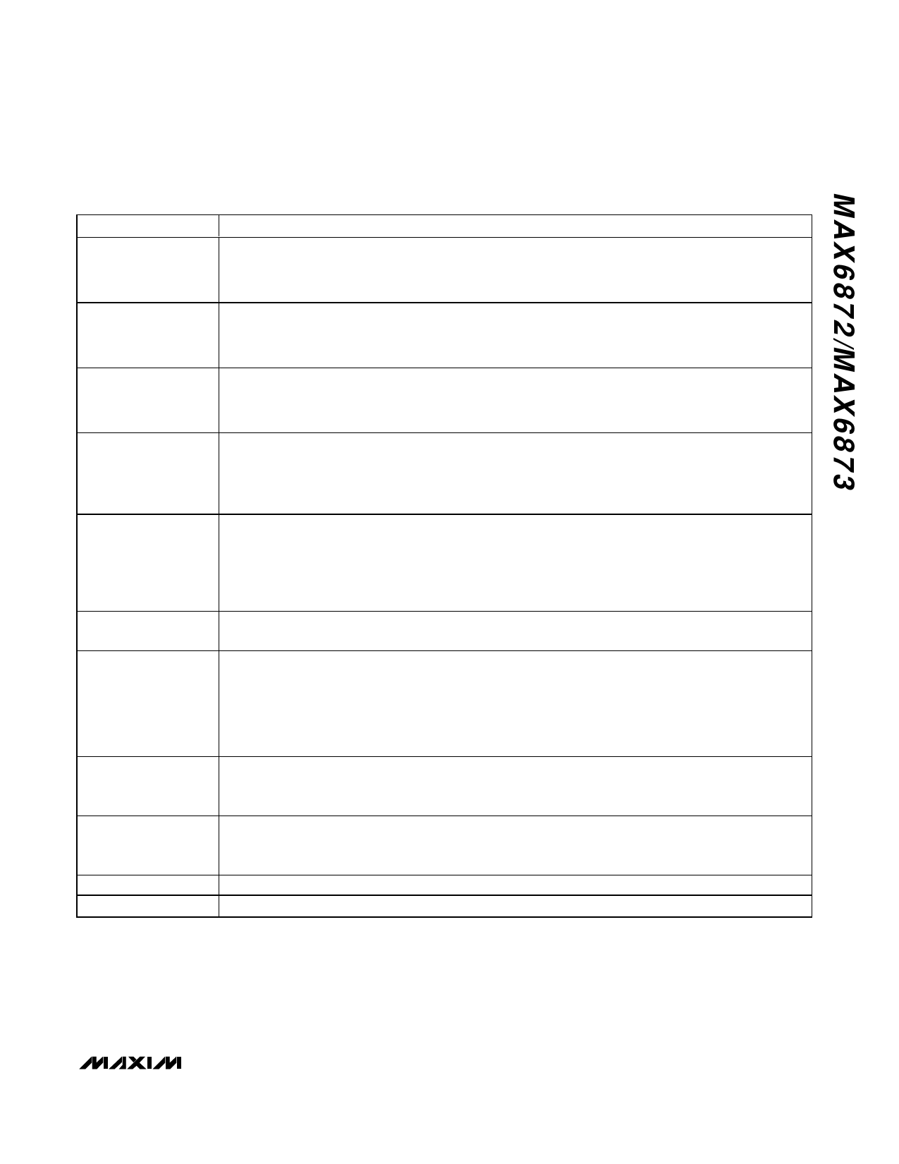
EEPROM-Programmable, Hex/Quad,
Power-Supply Sequencers/Supervisors
Table 1. Programmable Features
FEATURE
DESCRIPTION
High-Voltage Input
(IN1)
• Primary undervoltage threshold
• Secondary overvoltage or undervoltage threshold
• +2.5V to +13.2V threshold in 50mV increments
• +1.25V to +7.625V threshold in 25mV increments
Bipolar-Voltage Input
(IN2)
Positive-Voltage Input
IN3–IN6 (MAX6872),
IN3–IN4 (MAX6873)
• Primary undervoltage threshold
• Secondary overvoltage or undervoltage threshold
• ±2.5V to ±15.25V threshold in 50mV increments
• ±1.25V to ±7.625V threshold in 25mV increments
• Primary undervoltage threshold
• Secondary overvoltage or undervoltage threshold
• +1V to +5.5V threshold in 20mV increments
• +0.5V to +3.05V threshold in 10mV increments
• Active high or active low
Programmable Outputs • Open-drain, weak pullup, or charge-pump output
PO1–PO4 (MAX6872), • Weak pullup to IN3–IN6 (IN3 or IN4 for MAX6873) or ABP
PO1–PO2 (MAX6873) • Dependent on MR, MARGIN, IN_, GPI1–GPI4 , WD1 and WD2, and/or PO_
• Programmable timeout periods of 25µs, 1.5625ms, 6.25ms, 25ms, 50ms, 200ms, 400ms, or 1.6s
• Active high or active low
Programmable Outputs
PO5–PO8 (MAX6872),
PO3–PO5 (MAX6873)
•
•
•
•
Open-drain, weak pullup, or push-pull output
Weak pullup to IN3–IN6 (IN3 or IN4 for MAX6873) or ABP
Push-pull to IN3–IN6 (IN3 or IN4 for MAX6873)
Dependent on MR, MARGIN, IN_, GPI1–GPI4 , WD1 and WD2, and/or PO_
• Programmable timeout periods of 25µs, 1.5625ms, 6.25ms, 25ms, 50ms, 200ms, 400ms, or 1.6s
General-Purpose Logic • Active high or active low logic levels
Inputs (GPI1–GPI4) • Configure GPI_ as inputs to watchdog timers or programmable output stages
Watchdog Timers
• Clear dependent on any combination of one GPI_ input and one programmable output, a GPI_ input
only, or a programmable output only
• Initial watchdog timeout period of 6.25ms, 25ms, 100ms, 400ms, 1.6s, 6.4s, 25.6s, or 102.4s
• Normal watchdog timeout period of 6.25ms, 25ms, 100ms, 400ms, 1.6s, 6.4s, 25.6s, or 102.4s
• Watchdog enable/disable
• Initial watchdog timeout period enable/disable
Manual Reset Input
(MR)
• Forces PO_ into the active output state when MR = GND
• PO_ deassert after MR releases high and the PO_ timeout period expires
• PO_ cannot be a function of MR only
Margining Input
(MARGIN)
Write Disable
Configuration Lock
• Holds PO_ in existing state or asserts PO_ to a programmed output state, independent of changes in
monitored inputs or watchdog timers, when MARGIN = GND
• Overrides MR when both assert at the same time
• Locks user EEPROM based on PO_
• Locks configuration EEPROM
______________________________________________________________________________________ 13
Share Link: 