MAX6873 データシートの表示(PDF) - Maxim Integrated
部品番号
コンポーネント説明
メーカー
MAX6873 Datasheet PDF : 48 Pages
| |||
EEPROM-Programmable, Hex/Quad,
Power-Supply Sequencers/Supervisors
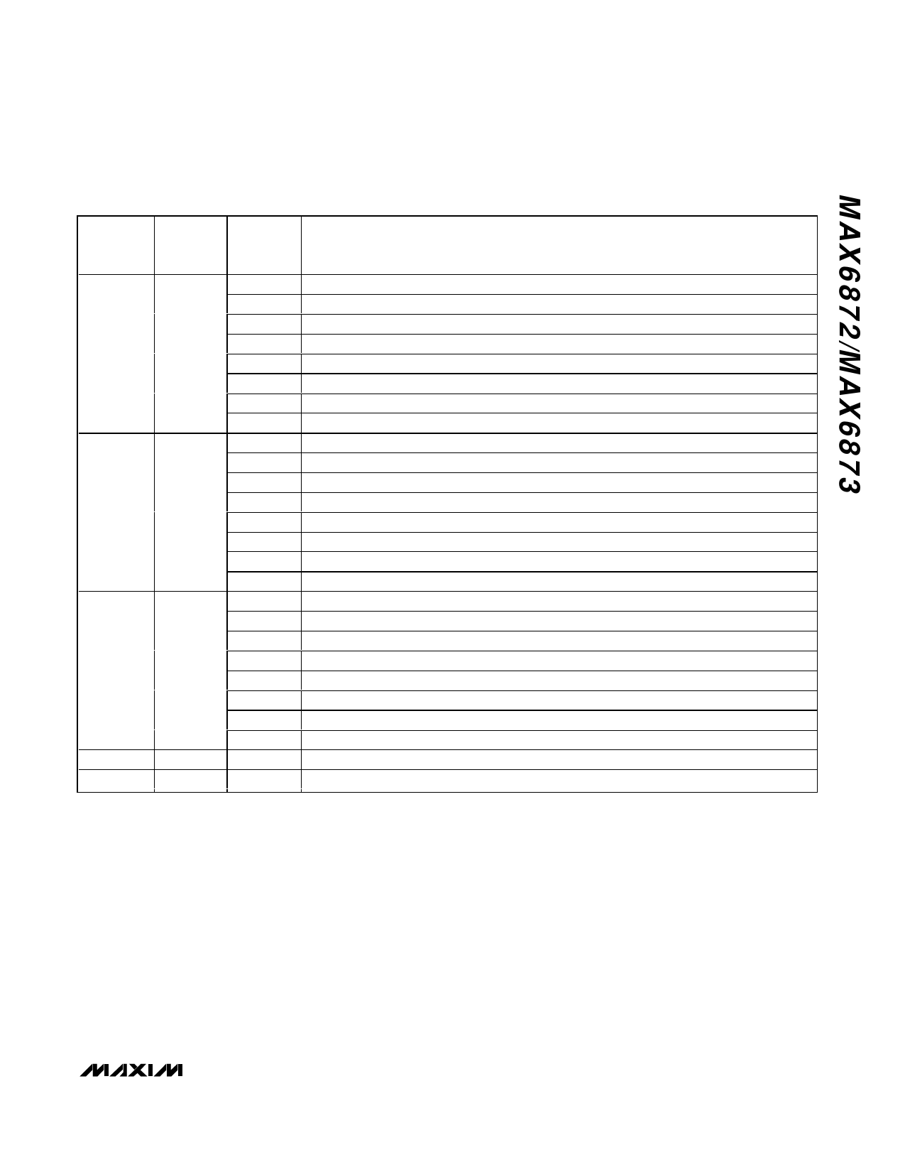
Table 9. PO2 (MAX6872 Only) Output Dependency
REGISTER
ADDRESS
EEPROM
MEMORY
ADDRESS
BIT
OUTPUT ASSERTION CONDITIONS
[0]
1 = PO2 assertion depends on IN1 primary undervoltage threshold (Table 2).
[1]
1 = PO2 assertion depends on IN2 primary undervoltage threshold (Table 3).
[2]
1 = PO2 assertion depends on IN3 primary undervoltage threshold (Table 4).
[3]
1 = PO2 assertion depends on IN4 primary undervoltage threshold (Table 4).
12h
8012h
[4]
1 = PO2 assertion depends on IN5 primary undervoltage threshold (Table 4).
[5]
1 = PO2 assertion depends on IN6 primary undervoltage threshold (Table 4).
[6]
1 = PO2 assertion depends on watchdog 1 (Tables 25 and 26).
[7]
1 = PO2 assertion depends on watchdog 2 (Tables 25 and 26).
[0]
1 = PO2 assertion depends on IN1 secondary undervoltage/overvoltage threshold (Table 2).
[1]
1 = PO2 assertion depends on IN2 secondary undervoltage/overvoltage threshold (Table 3).
[2]
1 = PO2 assertion depends on IN3 secondary undervoltage/overvoltage threshold (Table 4).
[3]
1 = PO2 assertion depends on IN4 secondary undervoltage/overvoltage threshold (Table 4).
13h
8013h
[4]
1 = PO2 assertion depends on IN5 secondary undervoltage/overvoltage threshold (Table 4).
[5]
1 = PO2 assertion depends on IN6 secondary undervoltage/overvoltage threshold (Table 4).
[6]
1 = PO2 assertion depends on GPI1 (Table 5).
[7]
1 = PO2 assertion depends on GPI2 (Table 5).
[0]
1 = PO2 assertion depends on GPI3 (Table 5).
[1]
1 = PO2 assertion depends on GPI4 (Table 5).
[2]
1 = PO2 assertion depends on PO1 (Table 8).
14h
8014h
[3]
1 = PO2 assertion depends on PO3 (Tables 10 and 11).
[4]
1 = PO2 assertion depends on PO4 (Tables 12 and 13).
[5]
1 = PO2 assertion depends on PO5 (Tables 14 and 15).
[6]
1 = PO2 assertion depends on PO6 (Tables 16 and 17).
[7]
1 = PO2 assertion depends on PO7 (Table 18).
15h
8015h
40h
8040h
[0]
1 = PO2 assertion depends on PO8 (Table 19).
[1]
1 = PO2 asserts when MR = low (Table 6).
age threshold, and the states of GPI2 and WD1. Write
ones to R19h[6, 0] and R1Ah[7] to configure Product 2
as indicated. IN1 must be above the primary undervolt-
age threshold (Table 2), GPI2 must be inactive (Table
5), and the WD1 timer must not have expired (Tables 25
and 26) for Product 2 to be a logical 1. Product 2 is
equivalent to the logic statement: V1A • GPI2 • WD1.
PO3 deasserts if either Product 1 or Product 2 is a logi-
cal 1. The logical statement: Product 1 + Product 2
determines the state of PO3.
Table 8 only applies to PO1 of the MAX6872. Write a 0
to a bit to make the PO1 output independent of the
respective signal (IN1–IN6 primary or secondary
thresholds, WD1 or WD2, GPI1–GPI4, MR, or other pro-
grammable outputs).
Table 9 only applies to PO2 of the MAX6872. Write a 0
to a bit to make the PO2 output independent of the
respective signal (IN1–IN6 primary or secondary
thresholds, WD1 or WD2, GPI1–GPI4, MR, or other pro-
grammable outputs).
______________________________________________________________________________________ 19
Share Link: 