MAX6875 データシートの表示(PDF) - Maxim Integrated
部品番号
コンポーネント説明
メーカー
MAX6875 Datasheet PDF : 40 Pages
| |||
EEPROM-Programmable, Hex/Quad,
Power-Supply Sequencers/Supervisors
GPI1–GPI4 (MAX6874)/GPI1–GPI3 (MAX6875)
The GPI1–GPI4 programmable logic inputs control
power-supply sequencing (programmable outputs),
reset/interrupt signaling, and watchdog functions (see
the Configuring the Watchdog Timer (Registers
3Ch–3Dh) section). Configure GPI1–GPI4 for active-low
or active-high logic (Table 5). GPI1–GPI4 internally pull
down to GND through a 10µA current sink.
MR
The manual reset (MR) input initiates a reset condition.
Register 40h determines the programmable outputs that
assert while MR is low (Table 6). All affected program-
mable outputs remain asserted (see the Programmable
Outputs section) for their PO_ timeout periods after MR
releases high. An internal 10µA current source pulls MR
to DBP. Leave MR unconnected or connect to DBP if
unused. A programmable output cannot depend solely
on MR.
MARGIN
MARGIN allows system-level testing while power supplies
exceed the normal ranges. Drive MARGIN low to hold the
programmable outputs in their state while system-level
testing occurs. Leave MARGIN unconnected or connect
to DBP if unused. An internal 10µA current source pulls
MARGIN to DBP. The state of each programmable output
does not change while MARGIN = GND. MARGIN over-
rides MR if both assert at the same time.
Programmable Outputs
The MAX6874 features eight programmable outputs
while the MAX6875 features five programmable outputs.
Program the open-drain outputs as active-high or
active-low. During power-up, the programmable outputs
pull to GND with an internal 10µA current sink for 1V <
VABP < VUVLO. The programmable outputs remain in
their active states until their respective timeout periods
(PO_) expire and all of the programmed conditions are
met for each output. Any output programmed to depend
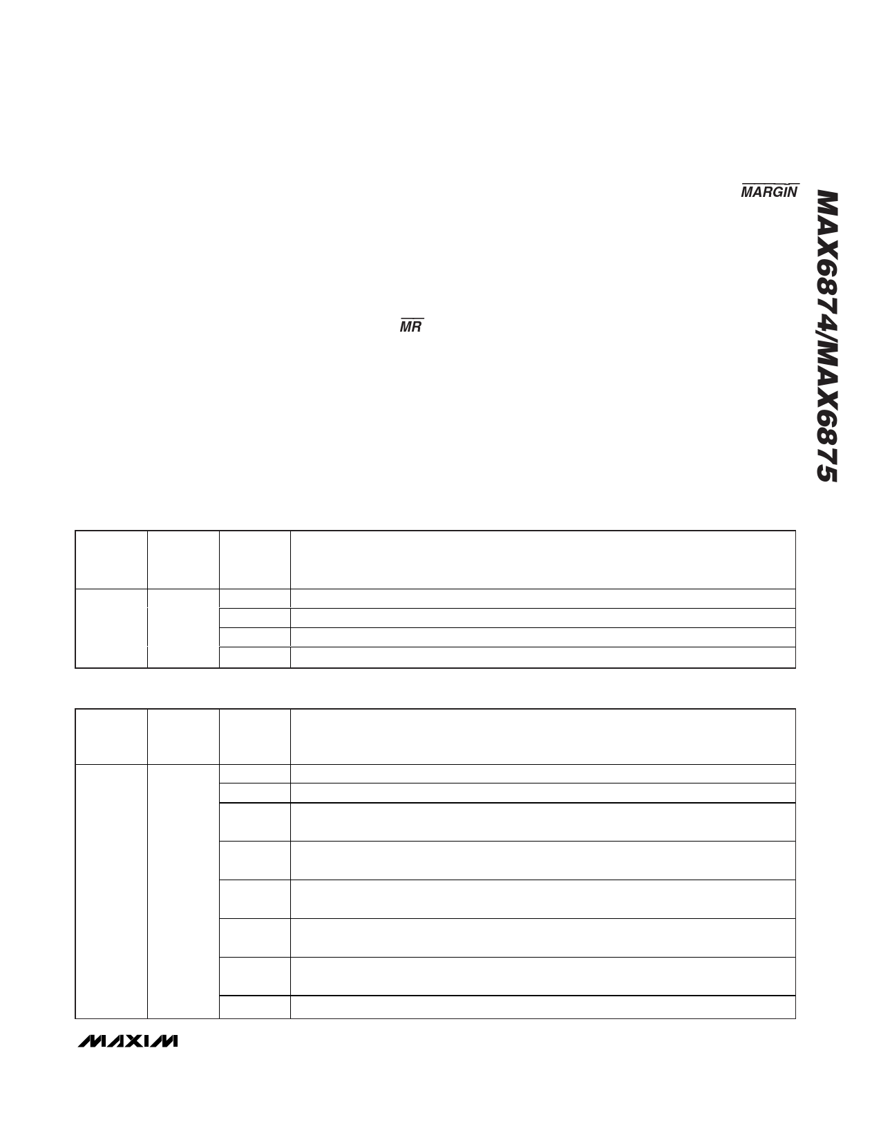
Table 5. GPI1–GPI4 Active Logic States
REGISTER
ADDRESS
EEPROM
MEMORY
ADDRESS
3Bh
803Bh
BIT
RANGE
[0]
[1]
[2]
[3]
DESCRIPTION
GPI1. 0 = active low. 1 = active high.
GPI2. 0 = active low. 1 = active high.
GPI3. 0 = active low. 1 = active high.
GPI4 (MAX6874 only). 0 = active low. 1 = active high.
Table 6. Programmable Output Behavior and MR
REGISTER
ADDRESS
EEPROM
MEMORY
ADDRESS
BIT
RANGE
DESCRIPTION
[0]
PO1 (MAX6874 only). 0 = PO1 independent of MR. 1 = PO1 asserts when MR = low.
[1]
PO2 (MAX6874 only). 0 = PO2 independent of MR. 1 = PO2 asserts when MR = low.
[2]
PO3 (MAX6874)/PO1 (MAX6875). 0 = PO3/PO1 independent of MR.
1 = PO3/PO1 asserts when MR = low.
[3]
PO4 (MAX6874)/PO2 (MAX6875). 0 = PO4/PO2 independent of MR.
1 = PO4/PO2 asserts when MR = low.
40h
8040h
[4]
PO5 (MAX6874)/PO3 (MAX6875). 0 = PO5/PO3 independent of MR.
1 = PO5/PO3 asserts when MR = low.
[5]
PO6 (MAX6874)/PO4 (MAX6875). 0 = PO6/PO4 independent of MR.
1 = PO6/PO4 asserts when MR = low.
[6]
PO7 (MAX6874)/PO5 (MAX6875). 0 = PO7/PO5 independent of MR.
1 = PO7/PO5 asserts when MR = low.
[7]
PO8 (MAX6874 only). 0 = PO8 independent of MR. 1 = PO8 asserts when MR = low.
______________________________________________________________________________________ 15
Share Link: 