MAX6876 データシートの表示(PDF) - Maxim Integrated
部品番号
コンポーネント説明
メーカー
MAX6876 Datasheet PDF : 39 Pages
| |||
EEPROM-Programmable, Quad,
Power-Supply Tracker/Sequencer Circuit
ELECTRICAL CHARACTERISTICS (continued)
(VCC, IN1–IN4 = +2.7V to +5.5V; ENABLE = MARGIN = MR = ABP = TRKEN; TA = -40°C to +85°C, unless otherwise specified.
Typical values are at TA = +25°C.) (Note 1)
Note 5: The MAX6876 programmed as a single device; GATE timeout has counted prior to beginning each sequence of power-up.
GATE timeout is not enabled during power-down or when the device is programmed as a master/slave.
Note 6: The MAX6876 programmed as a single device, the autoretry time begins to count at the assertion of the FAULT signal.
The MAX6876 programmed as a master/slave device; the autoretry time begins to count at the deassertion of the
common FAULT signal.
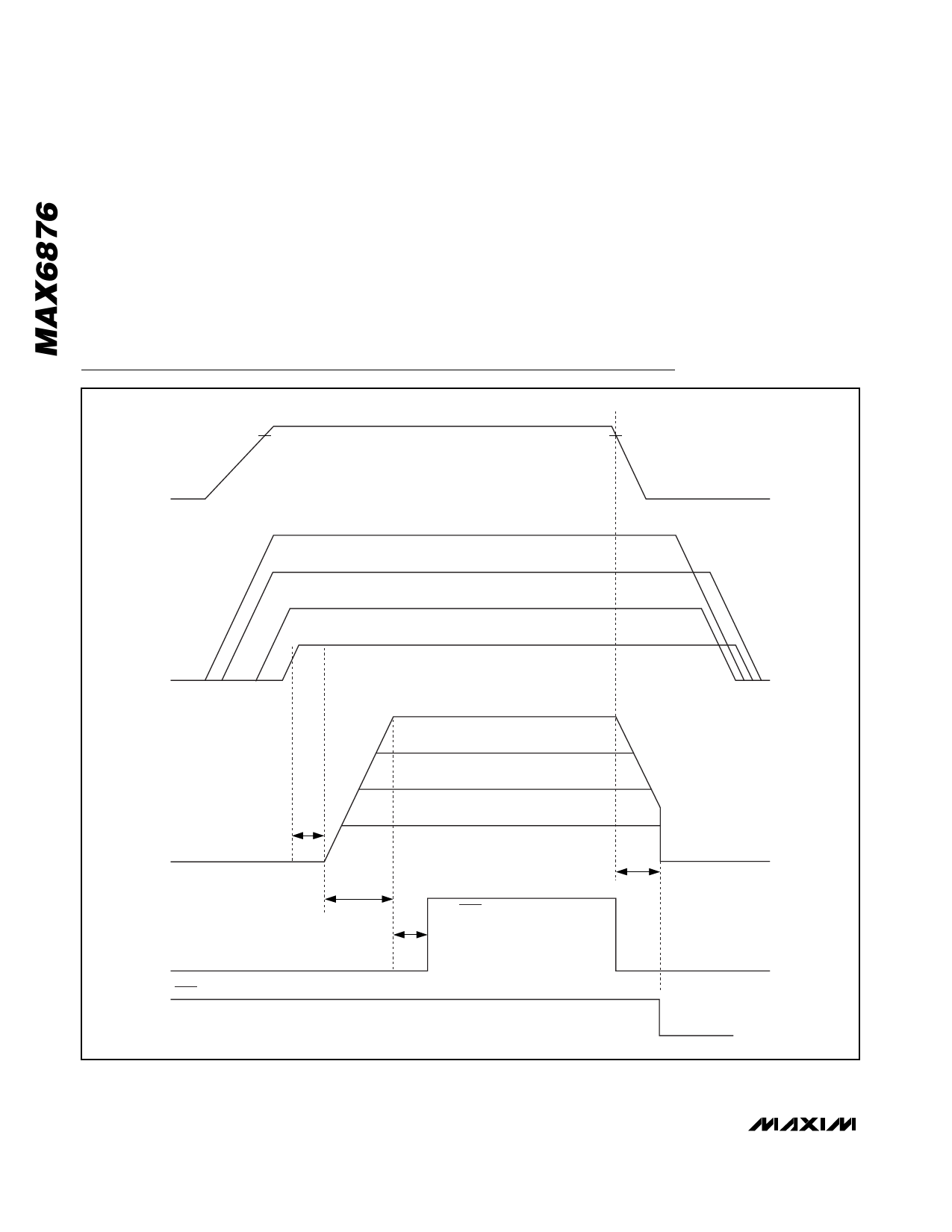
Timing Diagrams
VTRKEN
BUS VOLTAGE MONITORED THROUGH TRKEN INPUT
VTRKEN
GND
IN1 = 3.3V
IN2 = 2.5V
IN3 = 1.8V
IN4 = 1.5V
MONITORED THROUGH SET THRESHOLDS ON IN_
GND
INPUTS (EEPROM-SELECTABLE)
EEPROM-
ADJUSTED
SLEW RATE
OUT1 = 3.3V
OUT2 = 2.5V
OUT3 = 1.8V
OUT4 = 1.5V
tGATE
GND
<tFAULTUP
>tFAULTDOWN
tRESET
RESET
GND
FAULT
GND
Figure 1. Tracking Timing Diagram
6 _______________________________________________________________________________________
Share Link: 