MAX6885 データシートの表示(PDF) - Maxim Integrated
部品番号
コンポーネント説明
メーカー
MAX6885 Datasheet PDF : 34 Pages
| |||
EEPROM-Programmable, Hex
Power-Supply Supervisory Circuits
The MAX6884/MAX6885 feature a watchdog timer with
programmable initial and normal timeout periods from
6.25ms to 102.4s. WDO asserts when WDI is not tog-
gled from high-to-low or low-to-high within the appro-
priate watchdog timeout period. Program WDO to
assert RESET.
Program the MAX6884/MAX6885 to receive power
through IN1–IN4 or VCC (see the Powering the
MAX6884/MAX6885 section). Outputs remain asserted
while the voltage that is supplying the device is below
UVLO (2.5V) and above 1V (see Figure 1).
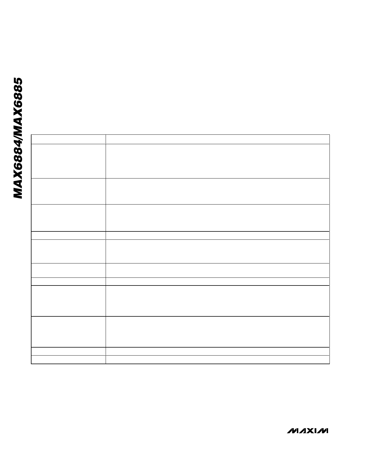
Table 1. Programmable Features
FEATURE
Input Voltages IN1–IN6
Programmable Output RESET
Programmable Output UV/OV
Programmable Output WDO
Watchdog Timer
VCC Power Mode
Manual Reset Input MR
Reference Input REFIN
DESCRIPTION
• Primary undervoltage threshold
• Secondary undervoltage or overvoltage threshold
• 1V to 5.8V thresholds in 20mV increments
• 0.5V to 3.05V thresholds in 10mV increments
• 0.1667V to 1.017V thresholds in 3.3mV increments in high-impedance mode
• Dependency on IN1–IN6, MR, UV/OV, and/or WDO
• Active-low, weak pullup, or open-drain output
• Programmable timeout periods of 25µs, 1.5625ms, 6.25ms, 25ms, 50ms, 200ms, 400ms, or
1.6s
• Dependency on IN1–IN6, MR, and/or RESET
• Active-low, weak pullup, or open-drain output
• Programmable timeout periods of 25µs, 1.5625ms, 6.25ms, 25ms, 50ms, 200ms, 400ms, or
1.6s
• Active-low, weak pullup, or open-drain output
• Initial watchdog timeout period of 6.25ms, 25ms, 100ms, 400ms, 1.6s, 6.4s, 25.6s, or 102.4s
• Normal watchdog timeout period of 6.25ms, 25ms, 100ms, 400ms, 1.6s, 6.4s, 25.6s, or 102.4s
• Watchdog enable/disable
• Programs whether the device is powered from the highest IN_ input or from an external supply
connected to VCC
• Program RESET or UV/OV to assert while MR is asserted
• Internal +1.25V reference voltage
• Goes high impedance when internal reference is selected
• External reference voltage input from 1.225V to 1.275V
• Sets ADC voltage range
10-Bit ADC*
• Samples voltages at IN1–IN6, AUXIN, and VCC
• Completes conversion of all eight inputs in 200ms
• Reference voltage sets ADC range
• Read ADC data from SMBus/I2C interface
Write Disable
Configuration Lock
• Locks user EEPROM based on RESET or UV/OV assertion
• Locks configuration registers and EEPROM
*ADC does not affect programmable outputs.
10 ______________________________________________________________________________________
Share Link: 