MAX6886 データシートの表示(PDF) - Maxim Integrated
部品番号
コンポーネント説明
メーカー
MAX6886 Datasheet PDF : 13 Pages
| |||
Pin-Selectable, Hex Power-Supply
Supervisory Circuit
Detailed Description
The MAX6886 pin-selectable, multivoltage supply
supervisor monitors six voltage-detector inputs and one
watchdog input. RESET asserts when any of the config-
ured input thresholds have been reached, MR is assert-
ed, or the watchdog timer expires. MARGIN allows a
system to be tested without RESET being asserted.
Logic inputs TH0–TH4 select 1 of 32 threshold sets for
inputs IN1–IN6 (see Table 2, Threshold Options).
Inputs in Table 2 that contain ADJ for inputs allow
external resistor voltage-dividers to be connected to
create additional thresholds.
RESET is an open-drain acitve-low output and asserts
when MR is low, the watchdog timer expires, or any
voltage at IN1–IN6 falls below its respective threshold.
The default RESET time delay is 200ms and custom
timeout periods are set by connecting an external
capacitor from SRT to GND. The default watchdog nor-
mal and initial timeout periods are 1.6s and 102.4s,
respectively. The normal and initial watchdog timeout
periods can be adjusted by connecting an external
capacitor from SWT to GND.
Powering the MAX6886
The MAX6886 derives power from the voltage-detector
inputs IN1–IN4 or through an externally supplied VCC.
A virtual diode-ORing scheme selects the positive input
that supplies power to the device (see the Functional
Diagram). The highest input voltage on IN1–IN4 sup-
plies power to the device. One of IN1–IN4 must be at
least 2.7V to ensure proper operation.
Internal hysteresis ensures that the supply input that
initially powered the device continues to power the
device when multiple input voltages are within 50mV of
each other.
VCC powers the analog circuitry and is the bypass con-
nection for the MAX6886 internal supply. Bypass VCC
to GND with a 1µF ceramic capacitor installed as close
to the device as possible. The internal supply voltage,
measured at VCC, equals the maximum of IN1–IN4. If
VCC is externally supplied, VCC must be at least 200mV
higher than any voltage applied to IN1–IN4 and VCC
must be brought up first. VCC always powers the
device when all IN_ are factory set as “ADJ.” Do not
use the internally generated VCC to provide power to
external circuitry.
The MAX6886 generates a digital supply voltage at DBP
for the internal logic circuitry and RESET. Bypass DBP
to GND with a 1µF ceramic capacitor installed as close
to the device as possible. The nominal DBP output volt-
age is 2.55V. Do not use DBP to provide power to exter-
nal circuitry.
Inputs
The MAX6886 contains multiple logic and voltage-
detector inputs. Each voltage-detector input is moni-
tored for undervoltage thresholds.
Voltage-Detector Inputs (IN_)
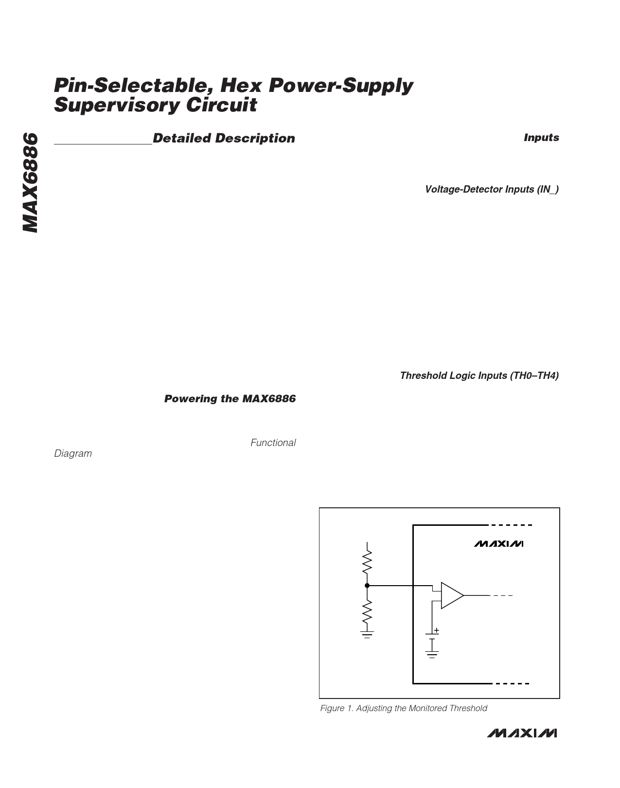
The MAX6886 offers several monitor options with both
pin-selectable and adjustable reset thresholds. The
threshold voltage at each adjustable IN_ input is typi-
cally 0.6V. To monitor a voltage >0.6V, connect a resis-
tor-divider network to the circuit as shown in Figure 1.
VIN_TH = VTH (R1 + R2) / R2 (Equation 1)
where VIN_TH is the desired reset threshold voltage for
the respective IN_ and VTH is the input threshold (0.6V).
Resistors R1 and R2 can have very high values to mini-
mize current consumption due to low-leakage currents.
Set R2 to some conveniently high value (10kΩ, for
example) and calculate R1 based on the desired reset
threshold voltage, using the following formula:
R1 = R2 x (VIN_TH/VTH - 1)
Threshold Logic Inputs (TH0–TH4)
The TH0–TH4 logic inputs select the undervoltage
thresholds and tolerance of the IN1–IN6 voltage-detec-
tor inputs. TH0–TH4 define 32 unique options for the
supervisor functionality. Connect the respective TH_ to
GND for a logic 0 or to DBP for a logic 1. Tables 1 and
2 show the 32 unique threshold options available. TH4
sets the threshold tolerance of the undervoltage thresh-
old. A logic 1 selects a 5% supply tolerance and a
logic 0 selects a 10% supply tolerance. The MAX6886
logic determines which thresholds should be used for
VIN
R1
IN_
R2
MAX6886
0.6V
Figure 1. Adjusting the Monitored Threshold
8 _______________________________________________________________________________________
Share Link: 