MAX6887 データシートの表示(PDF) - Maxim Integrated
部品番号
コンポーネント説明
メーカー
MAX6887 Datasheet PDF : 13 Pages
| |||
Hex/Quad, Power-Supply Supervisory Circuits
At power-up, WDO goes high after tD-PO (see Figure 3).
The initial watchdog timeout period (tWDI) applies imme-
diately after WDO is high. The initial watchdog timeout
period allows the µP to perform its initialization process.
A normal watchdog timeout period (tWD) applies when-
ever WDI transitions from high to low after the initial
watchdog timeout period occurs. WDI monitors the tog-
gling output of the µP, indicating normal processor
behavior. If WDI does not toggle during the normal
watchdog timeout period (tWD), indicating that the
processor has stopped operating or is stuck in an infinite
execution loop, WDO goes low. WDO stays low until the
next transition on WDI. An initial watchdog timeout peri-
od (tWDI) starts when WDO goes high.
If WDO is connected to MR, the WDO will assert for a
short duration (~5µs), long enough to assert the RESET
output. Asserting RESET clears the watchdog timer and
WDO goes high. The reset output will remain asserted
for its timeout period after a watchdog fault. The watch-
dog timer stays cleared as long as RESET is low.
Applications Information
Layout and Bypassing
For better noise immunity, bypass each of the voltage-
detector inputs to GND with 0.1µF capacitors installed
as close to the device as possible. Bypass VCC and BP
to GND with 1µF capacitors installed as close to the
device as possible. VCC (when not externally supplied)
and BP are internally generated voltages and should
not be used to supply power to external circuitry.
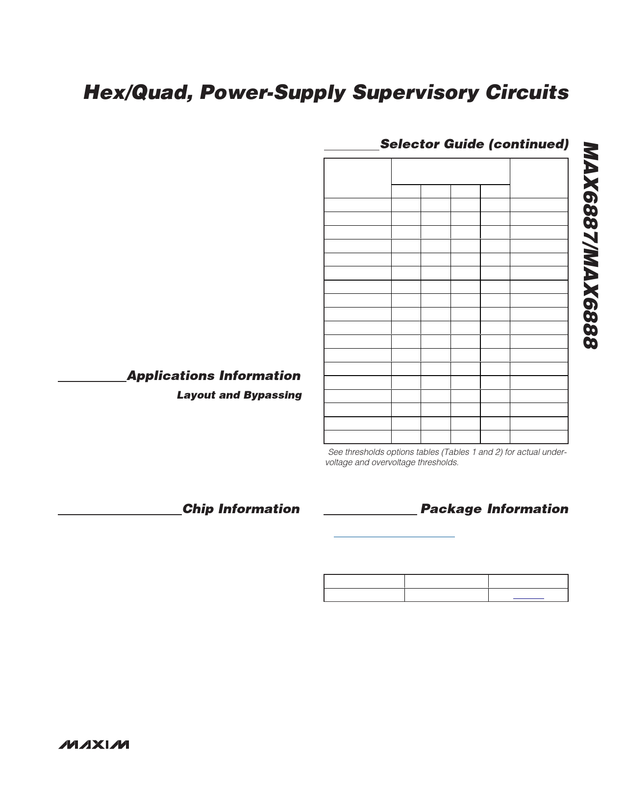
Selector Guide (continued)
PART
MAX6888AETE
MAX6888BETE
MAX6888CETE
MAX6888DETE
MAX6888EETE
MAX6888FETE
MAX6888GETE
MAX6888HETE
MAX6888QETE
MAX6888IETE
MAX6888JETE
MAX6888KETE
MAX6888LETE
MAX6888METE
MAX6888NETE
MAX6888OETE
MAX6888PETE
NOMINAL INPUT
VOLTAGE (V)*
IN1 IN2 IN3 IN4
5.0 3.3 2.5 1.8
5.0 3.3 2.5 Adj
5.0 3.3 1.8 Adj
3.3 2.5 1.8 1.5
3.3 2.5 1.8 Adj
3.3 2.5 1.5 Adj
3.3 2.5 Adj Adj
3.3 1.8 Adj Adj
Adj Adj Adj Adj
5.0 3.3 2.5 1.8
5.0 3.3 2.5 Adj
5.0 3.3 1.8 Adj
3.3 2.5 1.8 1.5
3.3 2.5 1.8 Adj
3.3 2.5 1.5 Adj
3.3 2.5 Adj Adj
3.3 1.8 Adj Adj
TOLERANCE
(%)
5
5
5
5
5
5
5
5
5
10
10
10
10
10
10
10
10
MAX6888RETE Adj Adj Adj Adj
10
*See thresholds options tables (Tables 1 and 2) for actual under-
voltage and overvoltage thresholds.
PROCESS: BiCMOS
Chip Information
Package Information
For the latest package outline information and land patterns, go
to www.maxim-ic.com/packages. Note that a "+", "#", or "-" in
the package code indicates RoHS status only. Package draw-
ings may show a different suffix character, but the drawing per-
tains to the package regardless of RoHS status.
PACKAGE TYPE PACKAGE CODE DOCUMENT NO.
16-TQFN-EP
T1655+2
21-0140
______________________________________________________________________________________ 11
Share Link: 