MAX6888 データシートの表示(PDF) - Maxim Integrated
部品番号
コンポーネント説明
メーカー
MAX6888 Datasheet PDF : 13 Pages
| |||
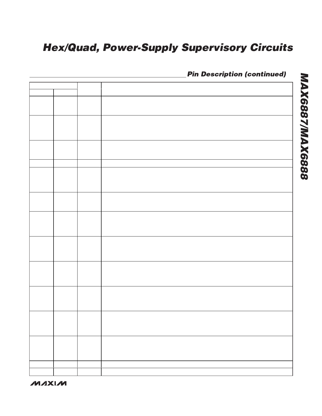
Hex/Quad, Power-Supply Supervisory Circuits
Pin Description (continued)
PIN
MAX6887 MAX6888
5
5
6
6
7
7
8
8
9
9
10
10
11
—
12
—
13
13
14
14
15
15
16
16
—
11, 12
—
—
NAME
MR
MARGIN
WDI
I.C.
VCC
BP
IN6
IN5
IN4
IN3
IN2
IN1
N.C.
EP
FUNCTION
Manual Reset Input. Pull MR low to assert RESET. Connect MR to WDO to generate resets
when the watchdog timer expires. Leave MR unconnected or connect to DBP if unused. MR is
internally pulled up to BP through a 10µA current source.
Margin Input. When MARGIN is pulled low, RESET is held in its existing state independent of
subsequent changes in monitored input voltages or the watchdog timer expiration. MARGIN is
internally pulled up to BP through a 10µA current source. Leave MARGIN unconnected or
connect to BP if unused. MARGIN overrides MR if both are asserted at the same time.
Watchdog Timer Input. Logic input for the watchdog timer function. If WDI is not strobed with a
valid low-to-high or high-to-low transition within the selected watchdog timeout period, WDO
asserts. WDI is internally pulled down to GND through a 10µA current sink.
Internal Connection. Leave unconnected.
Internal Power-Supply Voltage. Bypass VCC to GND with a 1µF ceramic capacitor as close to
the device as possible. VCC supplies power to the internal circuitry. VCC is internally powered
from the highest of the monitored IN1–IN4 voltages. Do not use VCC to supply power to external
circuitry. To externally supply VCC, see the Powering the MAX6887/MAX6888 section.
Bypass Voltage. The internally generated voltage at BP supplies power to internal logic and
output RESET. Connect a 1µF capacitor from BP to GND as close to the device as possible. Do
not use BP to supply power to external circuitry.
Input Voltage Detector 6. IN6 monitors both undervoltage and overvoltage conditions. See the
thresholds options (Tables 1 and 2) for available thresholds. IN6 cannot power the device. For
improved noise immunity, bypass IN6 to GND with a 0.1µF capacitor installed as close to the
device as possible.
Input Voltage Detector 5. IN5 monitors both undervoltage and overvoltage conditions. See the
thresholds options (Tables 1 and 2) for available thresholds. IN5 cannot power the device. For
improved noise immunity, bypass IN5 to GND with a 0.1µF capacitor installed as close to the
device as possible.
Input Voltage Detector 4. IN4 monitors both undervoltage and overvoltage conditions. See the
thresholds options (Tables 1 and 2) for available thresholds. Power the device through IN1–IN4
or VCC (see the Powering the MAX6887/MAX6888 section). For improved noise immunity,
bypass IN4 to GND with a 0.1µF capacitor installed as close to the device as possible.
Input Voltage Detector 3. IN3 monitors both undervoltage and overvoltage conditions. See the
thresholds options (Tables 1 and 2) for available thresholds. Power the device through IN1–IN4
or VCC (see the Powering the MAX6887/MAX6888 section). For improved noise immunity,
bypass IN3 to GND with a 0.1µF capacitor installed as close to the device as possible.
Input Voltage Detector 2. IN2 monitors both undervoltage and overvoltage conditions. See the
thresholds options (Tables 1 and 2) for available thresholds. Power the device through IN1–IN4
or VCC (see the Powering the MAX6887/MAX6888 section). For improved noise immunity,
bypass IN2 to GND with a 0.1µF capacitor installed as close to the device as possible.
Input Voltage Detector 1. IN1 monitors both undervoltage and overvoltage conditions. See the
thresholds options (Tables 1 and 2) for available thresholds. Power the device through IN1–IN4
or VCC (see the Powering the MAX6887/MAX6888 section). For improved noise immunity,
bypass IN1 to GND with a 0.1µF capacitor installed as close to the device as possible.
No Connection. Not internally connected.
Exposed Paddle. Internally connected to GND. Connect EP to GND or leave unconnected.
_______________________________________________________________________________________ 5
Share Link: 