NTE1710 データシートの表示(PDF) - NTE Electronics
部品番号
コンポーネント説明
メーカー
NTE1710 Datasheet PDF : 3 Pages
| |||
Electrical Characteristics (Cont’d): (VCC = 9V, TA = +25°C unless otherwise specified)
Parameter
Symbol
Test Conditions
Min Typ Max Unit
AGC Output Voltage
AGC Distortion
VO(AGC)
THD–A
Rec., AGC: ON, Rec. Out, Vi = 1kHz, 0.315mV
Rec., AGC: ON, Rec. Out, Vi = 1kHz, 31.5mV
315 445 570 mV
700 825 950 mV
– 0.15 0.3 %
R/P–SW Leakage Voltage
VLeak(P/R) Rec., Rec Out, Vi (PB Input) 1kHz 16mV,
Rec. Input Shorted
– 1.0 6.0 mV
P.B., Line Out, Vi (MIC Input) 1kHz 31.5mV,
P.B. Input Shorted
– 1.8 10 mV
Muting ON Leakage Voltage VLeak(Mute) Rec., Rec Out, Vi (MIC Input) 1kHz 0.5mV,
P.B. Input Shorted
– 50 100 µV
Total Supply Current
Mode handling Voltage
Playback Mode
Itot
P.B., Mute: OFF
V18–P
5.5 9.0 12.5 mA
0 – 0.7 V
Record Mode
Muting Holding Voltage
OFF Mode
V18–R
V17–OFF
3.5 – 7.0 V
0 – 0.9 V
ON Mode
V17–ON
2.4 – 4.0 V
Note 1. A capacitor of 10µF or over must be used between Pin11 and GND for the purpose of
preventing the AGC circuit oscillation when it is actually used.
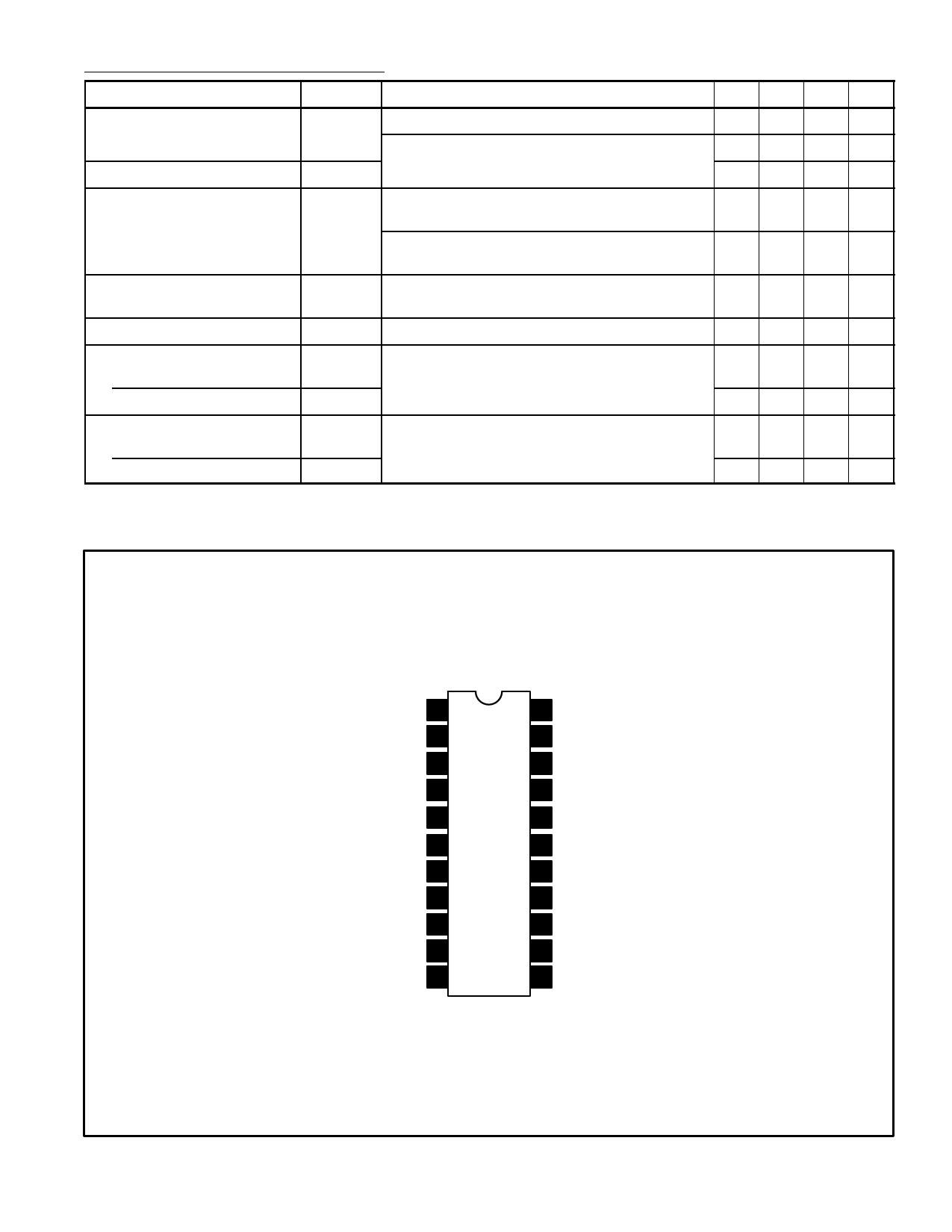
Pin Connection Diagram
EQ Input 1
EQ Neg Feedback 2
EQ Output 3
Buffer Input (Playback) 4
Buffer Feedback (Record) 5
Buffer Output 6
Line Input (Record) 7
Line Input (Playback) 8
Line Output 9
GND 10
AGC Control 11
22 MIC Input
21 MIC Neg Feedback
20 MIC Output
19 AGC Input
18 Record/Playback Switch
17 Muting Switch
16 Rec Input
15 Rec Neg Feedback
14 Rec Output
13 Reference Voltage
12 VCC
Share Link: 