NTE7047 データシートの表示(PDF) - NTE Electronics
部品番号
コンポーネント説明
メーカー
NTE7047 Datasheet PDF : 8 Pages
| |||
Notes (Cont’d):
Note19. The minimum value is obtained with a 1.8kΩ series resistor connected between Pin17 and
Pin25. The slicing level can be varied by changing the value of this resistor (a higher resist-
ance results in a larger value of the minimum sync pulse amplitude). The slicing level is inde-
pendent of the video information.
Note20. Frequency control is obtained by supplying a correction current to the oscillator RC–net-
word. This is achieved via a resistor connected between the phase 1 detector output and the
oscillator network. The oscillator can be adjusted to the correct frequency by:
S short–circuit the sync separator bias network (Pin25) to the voltage supply.
To avoid the necessity of a VCR switch, the time constant of the phase detector at strong
input signals is sufficiently short to obtain a stable picture during VCR playback. During the
vertical retrace period the time constant is even shorter so that VCR head errors are compen-
sated for at the beginning of the scan. During weak signal conditions (information derived
from the AGC circuit) the time constant is increased to obtain a good noise immunity.
Note21. This figure is valid for an external load impedance of 82kΩ connected between Pin28 and
the shift adjustment potentiometer.
Note22. The horizontal flyback input and the sandcastle output have been combined on Pin27. The
flyback pulse is clamped to a level of 4.5V. The minimum current to drive the second control
loop is 0.1mA.
Note23. The in–sync/out–of–sync and transmitter identification have been combined on Pin22. The
capacitor is charged during the sync pulse and discharged during the time difference be-
tween gating and sync pulsxe.
Note24. The vertical scan is synchronized by means of a divider system, therefore no adjustment is
required for the ramp generator. The divider detects whether the incoming signal has a verti-
cal frequency of 50Hz or 60Hz and corrects the vertical amplitude.
Note25. To avoid screenburn due to a collapse of the vertical deflection, a continuous blanking level
is inserted into the sandcastle pulse when the feedback voltage of the vertical deflection is
not within the specified limits.
Note26. These figures are based on sampled tests.
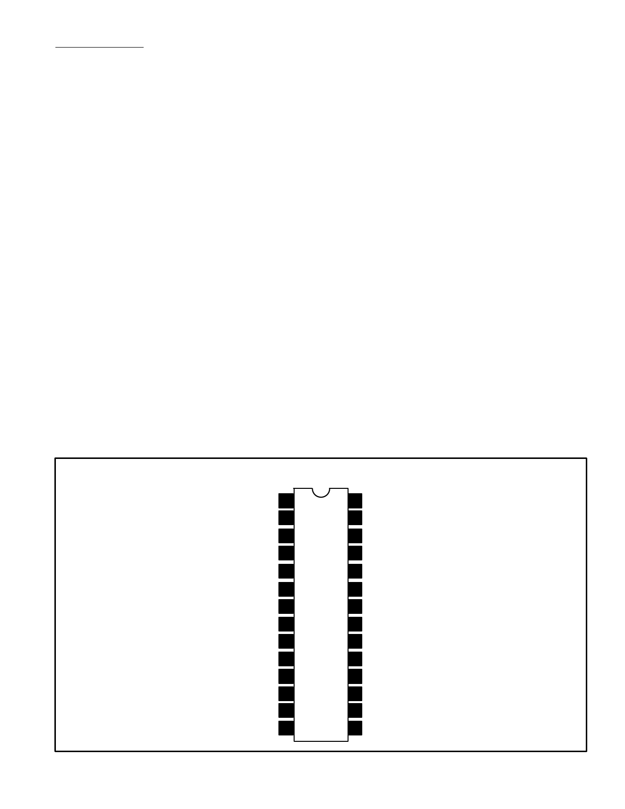
Pin Connection Diagram
AGC Takeover/X–Ray Protection 1
Vert Ramp Generator 2
Vertical Drive 3
Vertical Feeback 4
Tuner AGC 5
GND 6
VCC 7
Vision IF Input 8
Vision IF Input 9
IF AGC 10
Volume Control/Start Horiz OSC 11
Audio Output 12
Sound Demod 13
Sound IF Decouple 14
28 Phase 2 Detector
27 Sandcastle Output/Horiz Flyback Input
26 Horizontal Drive
25 Sync Separator
24 Phase 1 Detector
23 Horizontal OSC
22 Coincidence Detector
21 Vision Demod Tuned Ckt
20 Vision Demod Tuned Ckt
19 AFC S/H, AFC Switch
18 AFC Output
17 Video Output
16 GND
15 Sound IF Input
Share Link: 