2SB09560RL データシートの表示(PDF) - Panasonic Corporation
部品番号
コンポーネント説明
メーカー
2SB09560RL Datasheet PDF : 3 Pages
| |||
Transistors
This product complies with the RoHS Directive (EU 2002/95/EC).
2SB0956
Silicon PNP epitaxial planar type
For low-frequency output amplification
Complementary to 2SD1280
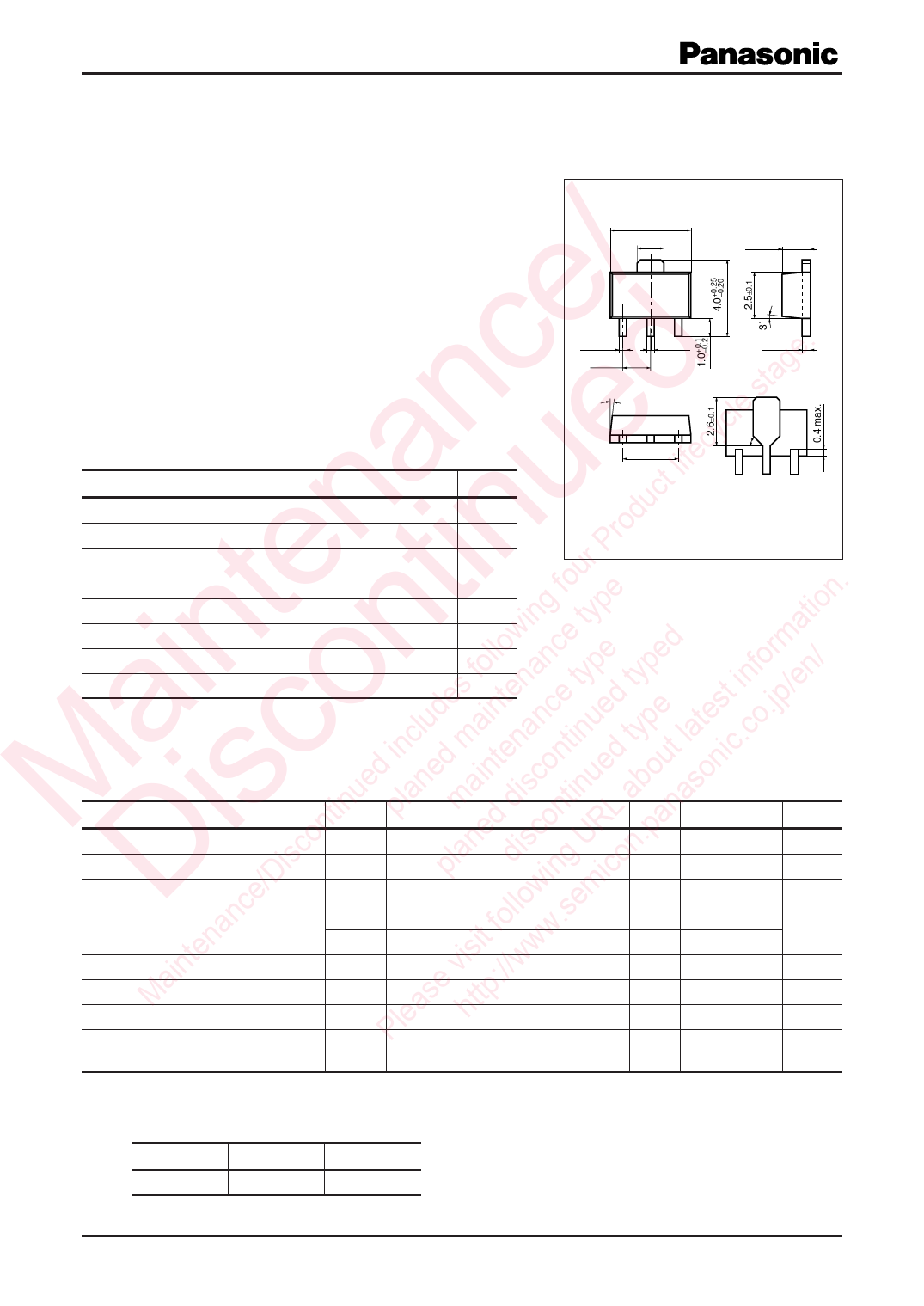
4.5±0.1
1.6±0.2
Unit: mm
1.5±0.1
/ ■ Features
• Large collector power dissipation PC
e . • Low collector-emitter saturation voltage VCE(sat)
ge • Mini Power type package, allowing downsizing of the equipment
c ta and automatic insertion through the tape packing and the maga-
n d le s zine packing.
a e lifecyc ■ Absolute Maximum Ratings Ta = 25°C
t Parameter
Symbol Rating
Unit
uc Collector-base voltage (Emitter open) VCBO
−20
V
n u rod Collector-emitter voltage (Base open) VCEO
−20
V
te tin r P Emitter-base voltage (Collector open) VEBO
−5
V
fou . Collector current
IC
−1
A
ing type tion Peak collector current
ICP
−2
A
w a Collector power dissipation *
PC
1
W
in n follo ance pe ped form / Junction temperature
Tj
150
°C
es ten e ty d ty t in /en Storage temperature
Tstg −55 to +150 °C
a o lud ain nc ue pe tes .jp Note) *: Print circuit board: Copper foil area of 1 cm2 or more, and the board
inc m na tin ty la .co thickness of 1.7 mm for the collector portion
1
0.4±0.08
1.5±0.1
23
0.5±0.08
3˚
0.4±0.04
45˚
3.0±0.15
Marking Symbol: H
1: Base
2: Collector
3: Emitter
MiniP3-F1 Package
M isctinued planedmaintediscontinued bout sonic ■ Electrical Characteristics Ta = 25°C ± 3°C
n L a na Parameter
Symbol
Conditions
Min
iscon laned isco UR .pa Collector-emitter voltage (Base open) VCEO IC = −1 mA, IB = 0
−20
d g on Emiter-base voltage (Collector open) VEBO IE = −10 µA, IC = 0
−5
e/D p win mic Collector-base cutoff current (Emitter open) ICBO VCB = −10 V, IE = 0
Danc follo .se Forward current transfer ratio *1
hFE1 *2 VCE = −2 V, IC = −500 mA
130
n it w hFE2 VCE = −2 V, IC = −1.5 A
50
ainte e vis ://ww Collector-emitter saturation voltage *1 VCE(sat) IC = −1 A, IB = −50 mA
M as ttp Base-emitter saturation voltage *1
VBE(sat) IC = −500 mA, IB = −50 mA
le h Transition frequency
fT
VCB = −6 V, IE = 50 mA, f = 200 MHz
P Collector output capacitance
Cob VCB = −6 V, IE = 0, f = 1 MHz
Typ Max
−1
280
− 0.5
−1.2
200
40
Unit
V
V
µA
V
V
MHz
pF
(Common base, input open circuited)
Note) 1. Measuring methods are based on JAPANESE INDUSTRIAL STANDARD JIS C 7030 measuring methods for transistors.
2. *1: Pulse measurement
*2: Rank classification
Rank
R
S
hFE1
130 to 210 180 to 280
Publication date: December 2002
SJC00062CED
1
Share Link: 