CR6202 データシートの表示(PDF) - Unspecified
部品番号
コンポーネント説明
メーカー
CR6202 Datasheet PDF : 14 Pages
| |||
CR6202
Application Information
1. Relationship between CT timing capacitance and switching frequency
CT capacitance is charged by 50uA constant current through internal current source to for the rise-up edge,
when the voltage is charged to 1.6V, the internal circuit will discharge CT with 1.9mA of pull-down current to
form the fall-down edge of the clock, and accomplish a clock cycle, which is about:
T=CT*48000 (S)
Fs=1/T (Hz)
Although the bipolar circuit can work under higher frequency, but for the switch of bipolar power, the
influence caused by switch loss for the storage time is still be considered. Generally, the appropriate switching
frequency is about below 70KHz. Under common application situation, CT capacitance of CR6202 can be
configured by 330PF, when the relevant working frequency is around 66KHz.
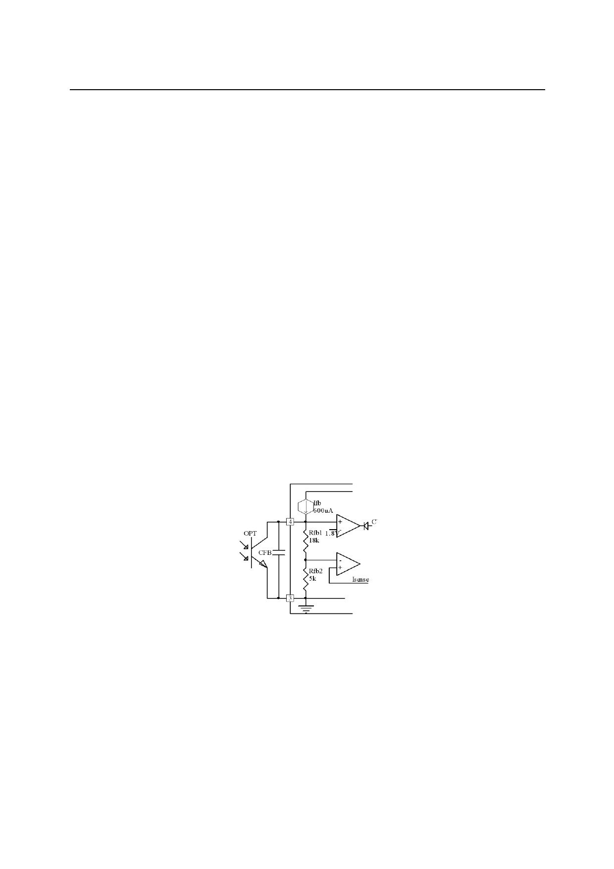
2. FB feedback and control
In normal working state, the voltage of FB will decide the value of the maximum switching current, the
higher the voltage is, the bigger the switching current is (it is only limited at the peak value). FB pins pull up
600uA power source internally, the pull-down resistance is about 23KΩ (it approximates the equivalent value).
In addition, when FB voltage is less than 1.8V, the oscillating cycle will be enlarged, the switching frequency
will declined, the more it is less than 1.8V, the lower the switching frequency is. The external FB capacitance
will influence the feedback bandwidth, so some external parameters will be affected, such as transient-state
characteristic.
As for the value of CFB capacitance, the typical application can be selected according to the frequency
character of feedback circuit between 10nF and 100nF. It is recommended to use 22nF.
3. Over temperature protection
The interior of IC integrates the function of over temperature protection. When the internal temperature of
the chip reaches 125ć, the over-heat protection circuit will work, it will pull down the clock signal, the
switching frequency will fall until the oscillator is turned off. As shown in the following figure
Aug.2008 V2.0
8/14
Share Link: 