EG3013 データシートの表示(PDF) - Unspecified
部品番号
コンポーネント説明
メーカー
EG3013 Datasheet PDF : 12 Pages
| |||
micro corp.
Input/Output Logic Table:
Input
HIN(Pin4)
LIN(Pin3)
0
0
0
1
1
0
1
1
EG3013 datasheet
Half-Bridge Driver
Output
HO(Pin7)
LO(Pin5)
0
1
0
0
0
0
1
0
From above logic table view, Case A: when HIN and LIN are low at same time, LO will output high to
turn on low side MOSFET and HO will output low to turn off high side MOSFET. Case B: when HIN and
low and LIN are high at same time, HO will output high to turn on high side MOSFET and LO will output
low to turn off low side MOSFET. Case C: when HIN goes low and LIN goes high or HIN goes high and
LIN goes low, HO and LO will simultaneously output low to turn off high and low side MOSFET, the
interlock and dead time functions prevent both outputs from being turned on simultaneously.
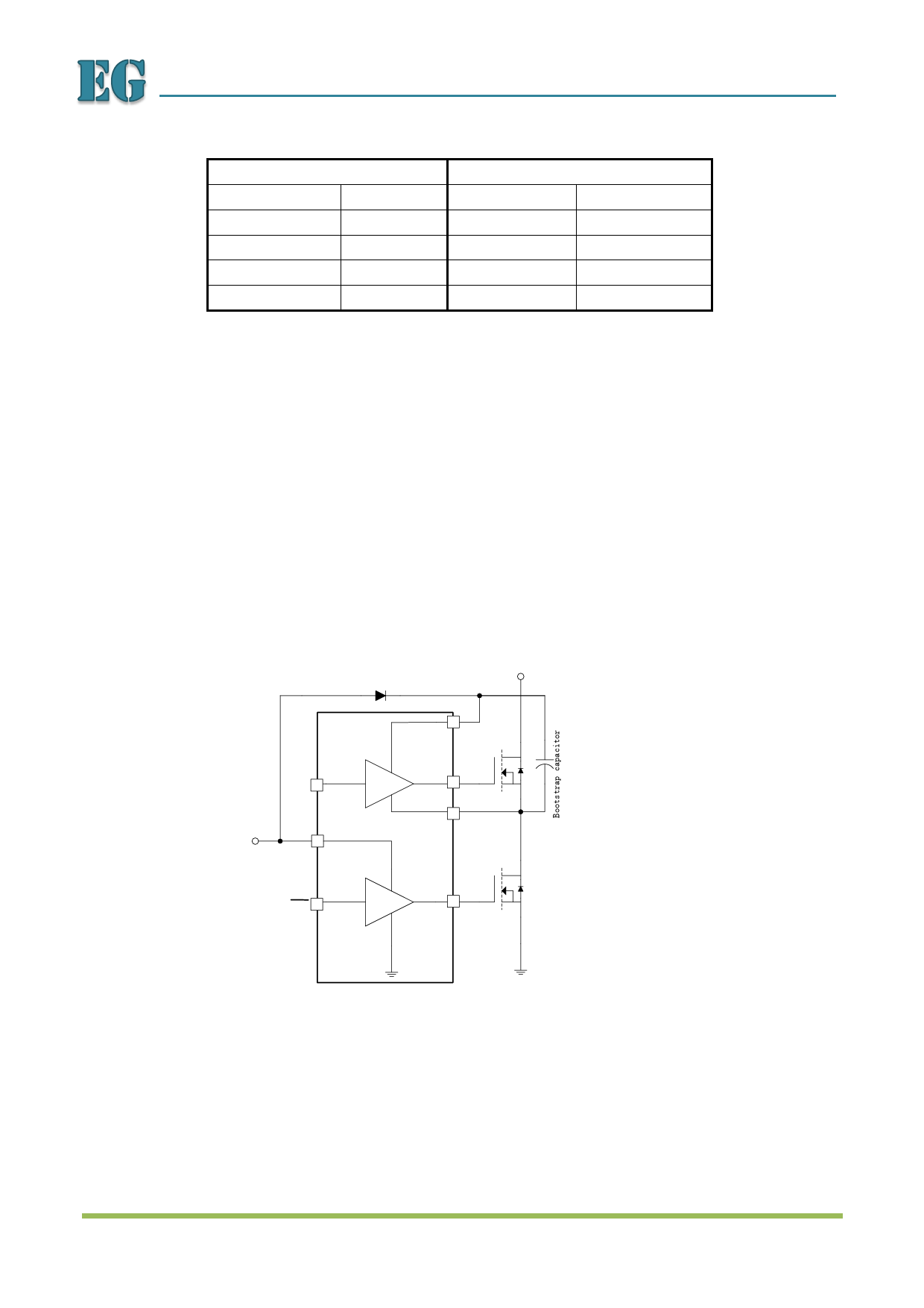
8.3 Bootstrap
The EG3013 uses a bootstrap structure, which has the advantage of being simply and low cost. The
Figure 8-3 will help to understand the operation of bootstrap circuit. The voltage at VCC forces current
through the internal bootstrap diode or external bootstrap diode, bootstrap capacitor and low side
MOSFET, which will charge the bootstrap capacitor to prepare it for driving the high side MOSFET.
External bootstrap diode
+48V
FR107
8 VB
HIN 2
+15V
VCC 1
VC
7 HO
6 VS
LIN 3
5 LO
EG3013
Figure 8-3. EG3013 Bootstrap circuit structure
Copyright © 2012 by EGmicro Corporation
www.EGmicro.com
10 / 11
Share Link: 