FDS6673BZ „Éá„Éľ„āŅ„ā∑„Éľ„Éą„ĀģŤ°®Á§ļÔľąPDFÔľČ - Fairchild Semiconductor
ťÉ®ŚďĀÁē™ŚŹ∑
„ā≥„É≥„ÉĚ„Éľ„Éć„É≥„ÉąŤ™¨śėé
„É°„Éľ„āę„Éľ
FDS6673BZ Datasheet PDF : 6 Pages
| |||
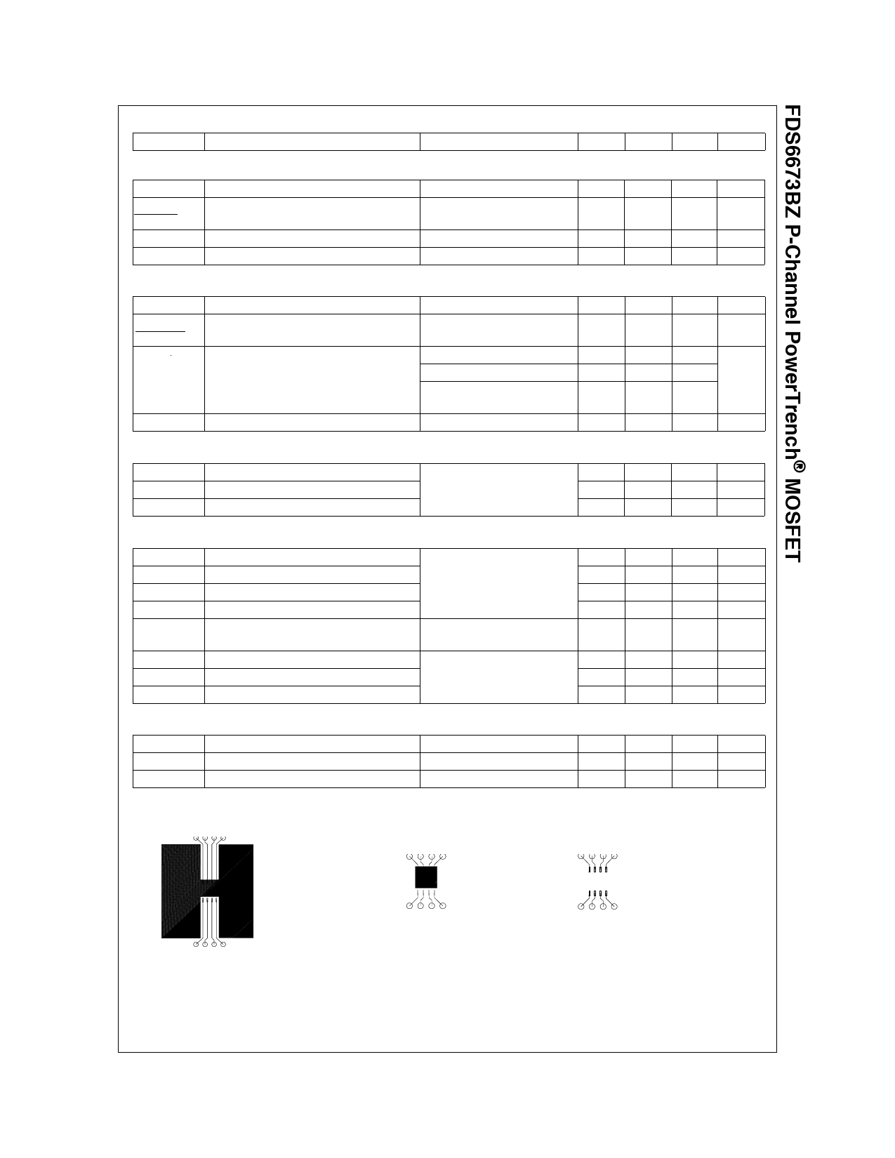
Electrical Characteristics TJ = 25¬įC unless otherwise noted
Symbol
Parameter
Test Conditions
Min Typ Max Units
Off Characteristics
BVDSS
‚ąÜBVDSS
‚ąÜTJ
IDSS
IGSS
Drain to Source Breakdown Voltage
Breakdown Voltage Temperature
Coefficient
Zero Gate Voltage Drain Current
Gate to Source Leakage Current
ID = -250¬ĶA, VGS = 0V
ID = -250¬ĶA, referenced to
25¬įC
VDS = -24V, VGS = 0V
VGS = ¬Ī25V, VDS = 0V
-30
V
-20
mV/¬įC
-1
¬ĶA
¬Ī10 ¬ĶA
On Characteristics (Note 2)
VGS(th)
‚ąÜVGS(th)
‚ąÜTJ
Gate to Source Threshold Voltage
Gate to Source Threshold Voltage
Temperature Coefficient
rDS(on)
Drain to Source On Resistance
gFS
Forward Transconductance
VGS = VDS, ID = -250¬ĶA
ID = -250¬ĶA, referenced to
25¬įC
VGS = -10V , ID = -14.5A
VGS = -4.5V, ID = -12A
VGS = -10V, ID = -14.5A
TJ = 125oC
VDS = -5V, ID = -14.5A
-1
-1.9
-3
V
8.1
mV/¬įC
6.5
7.8
9.6
12
m‚Ą¶
9.7
12
60
S
Dynamic Characteristics
Ciss
Coss
Crss
Input Capacitance
Output Capacitance
Reverse Transfer Capacitance
VDS = -15V, VGS = 0V,
f = 1.0MHz
3500 4700 pF
600 800 pF
600 900 pF
Switching Characteristics (Note 2)
td(on)
tr
td(off)
tf
Turn-On Delay Time
Rise Time
Turn-Off Delay Time
Fall Time
Qg
Total Gate Charge
Qg
Total Gate Charge
Qgs
Gate to Source Gate Charge
Qgd
Gate to Drain Charge
VDD = -15V, ID = -1A
VGS = -10V, RGS = 6‚Ą¶
VDS = -15V, VGS = -10V,
ID = -14.5A
VDS = -15V, VGS = -5V,
ID = -14.5A
14
26
ns
16
29
ns
225 36
ns
105 167
ns
88 124 nC
46
65
nC
8
nC
23.5
nC
Drain-Source Diode Characteristics
VSD
Source to Drain Diode Forward Voltage VGS = 0V, IS = -2.1A
trr
Reverse Recovery Time
IF = 14.5A, di/dt = 100A/¬Ķs
Qrr
Reverse Recovery Charge
IF = 14.5A, di/dt = 100A/¬Ķs
-0.7 -1.2
V
45
ns
34
nC
Notes:
1: RőłJA is the sum of the junction-to-case and case-to-ambient thermal resistance where the case thermal reference is defined as the solder mounting surface of the
drain pins. RőłJC is guaranteed by design while RőłCA is determined by the user‚Äôs board design.
a) 50 oC/W (10 sec)
when mounted on a 1 in2
pad of 2 oz copper
b) 105 oC/W when mounted
on a .04 in2 pad of 2 oz
copper
c) 125 oC/W when mounted
on a minimun pad
Scale 1 : 1 on letter size paper
2: Pulse Test: Pulse Width < 300¬Ķs, Duty Cycle < 2.0%.
3: The diode connected between the gate and source serves only as protection against ESD. No gate overvoltage rating is implied.
FDS6673BZ Rev. B
2
www.fairchildsemi.com
Share Link: 