LTC1729 データシートの表示(PDF) - Linear Technology
部品番号
コンポーネント説明
メーカー
LTC1729 Datasheet PDF : 16 Pages
| |||
LTC1729 Series
APPLICATIO S I FOR ATIO
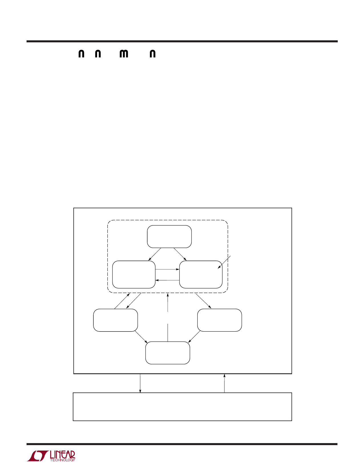
State Machine
The state machine is responsible for the following items:
1. When to start and stop the charger. The internal timer
must be initialized every time a new battery is installed
or when the input supply is applied.
2. When a battery is installed, the state machine must
determine if it is a new battery or if the previous battery
has been reinstalled.
3. When a deeply discharged battery is installed, trickle
charge conditioning must take place before the full
charge current.
The state machine diagram is shown in Figure 6. Note that
the Charge state includes the Precondition state, the
charger “ON” state and the Reset mode.
Reset and Hold are the two modes that will cause the
charger to stop charging (VC pin pulled low) and ignore the
state machine. The Reset mode clears all the timers and
forces the state machine to begin in the Charge state
(STATUS pin pulled low). This mode is only activated
momentarily at power-up or when the NTC pin is below the
Reset threshold. The other interrupt condition is called the
Hold mode. When the voltage on the NTC pin is above
2.79V (cold) or below 0.405V (hot), the state machine is
locked in the present state until the NTC pin voltage returns
to the proper range. While in the Hold mode, the charging
is disabled and the timers are frozen.
The charger is enabled only during the charger “ON” state.
There are three ways that the state machine can exit the
charger “ON” state. The first is for a 3-hour time-out which
is denoted as the time > tMAX transition to the Done state.
CHARGE
RESET MODE
IBAT = 0
STATUS = PULL-DOWN
VC = PULL-DOWN
VBAT < VMIN
VBAT > VMIN
PRECONDITION
IBAT = 12mA
STATUS = PULL-DOWN
VC = PULL-DOWN
tMAX = 1HR
VBAT > VMIN
VBAT < VMIN
CHARGER “ON”
IBAT = 1.3mA
STATUS = PULL-DOWN
VC = OPEN
tMAX = 3HR
NOTE: FOR STATUS
PULL-DOWN = HARD:
FOR CURRENT > C/10
PULL-DOWN = 50µA:
FOR CURRENT < C/10 FOR 3SEC
VBAT < VMAX
FOR MORE THAN 1SEC
VBAT > VMAX
PAUSE
IBAT = 0
STATUS = PULL-DOWN
VC = PULL-DOWN
VBAT > VMAX
FOR MORE THAN 1SEC
VBAT < VMAX
FOR MORE THAN 1SEC
NO BAT
IBAT = 0
STATUS = OPEN
VC = PULL-DOWN
TIME > tMAX
DONE
IBAT = 0
STATUS = OPEN
VC = PULL-DOWN
VBAT > VMAX
FOR MORE THAN 1SEC
VNTC > 2.79V OR
VNTC < 0.405V
HOLD MODE
IBAT = 0
STATUS = PREVIOUS STATUS
VC = PULL-DOWN
Figure 6. State Diagram
VNTC < 2.79V AND
VNTC > 0.405V
1729 F06
9
Share Link: 