MIC79050 データシートの表示(PDF) - Micrel
部品番号
コンポーネント説明
メーカー
MIC79050 Datasheet PDF : 14 Pages
| |||
MIC79050
Simple Charging
The MIC79050 is available in a three-terminal package, allow-
ing for extremely simple battery charging. When used with a
current-limited, low-power input supply, the MIC79050-4.2BS
completes a very simple, low-charge-rate, battery-charger
circuit. It provides the accuracy required for termination, while
a current-limited input supply offers the constant-current por-
tion of the algorithm.
Thermal Considerations
The MIC79050 is offered in three packages for the various
applications. The SOT-223 is most thermally efficient of
the three packages, with the power SOIC-8 and the power
MSOP-8 following suit.
Power SOIC-8 Thermal Characteristics
One of the secrets of the MIC79050’s performance is its
power SO-8 package featuring half the thermal resistance of
a standard SO-8 package. Lower thermal resistance means
more output current or higher input voltage for a given pack-
age size.
Lower thermal resistance is achieved by joining the four
ground leads with the die attach paddle to create a single-
piece electrical and thermal conductor. This concept has
been used by MOSFET manufacturers for years, proving
very reliable and cost effective for the user.
Thermal resistance consists of two main elements, θJC, or
thermal resistance junction to case and θCA, thermal resis-
tance case to ambient (Figure 8). θJC is the resistance from
the die to the leads of the package. θCA is the resistance
from the leads to the ambient air and it includes θCS, thermal
resistance case to sink, and θSA, thermal resistance sink to
ambient. Using the power SOIC-8 reduces the θJC dramati-
cally and allows the user to reduce θCA. The total thermal
resistance, θ JA, junction to ambient thermal resistance, is the
limiting factor in calculating the maximum power dissipation
capability of the device. Typically, the power SOIC-8 has a
θJC of 20°C/W, this is significantly lower than the standard
SOIC-8 which is typically 75°C/W. θCA is reduced because
pins 5-8 can now be soldered directly to a ground plane, which
significantly reduces the case to sink thermal resistance and
sink to ambient thermal resistance.
SOIC-8
qJA
qJC
qCA
ground plane
heat sink area
AMBIENT
printed circuit board
Figure 8. Thermal Resistance
Micrel, Inc.
The MIC79050 is rated to a maximum junction temperature
of 125°C. It is important not to exceed this maximum junction
temperature during operation of the device. To prevent this
maximum junction temperature from being exceeded, the
appropriate ground plane heat sink must be used.
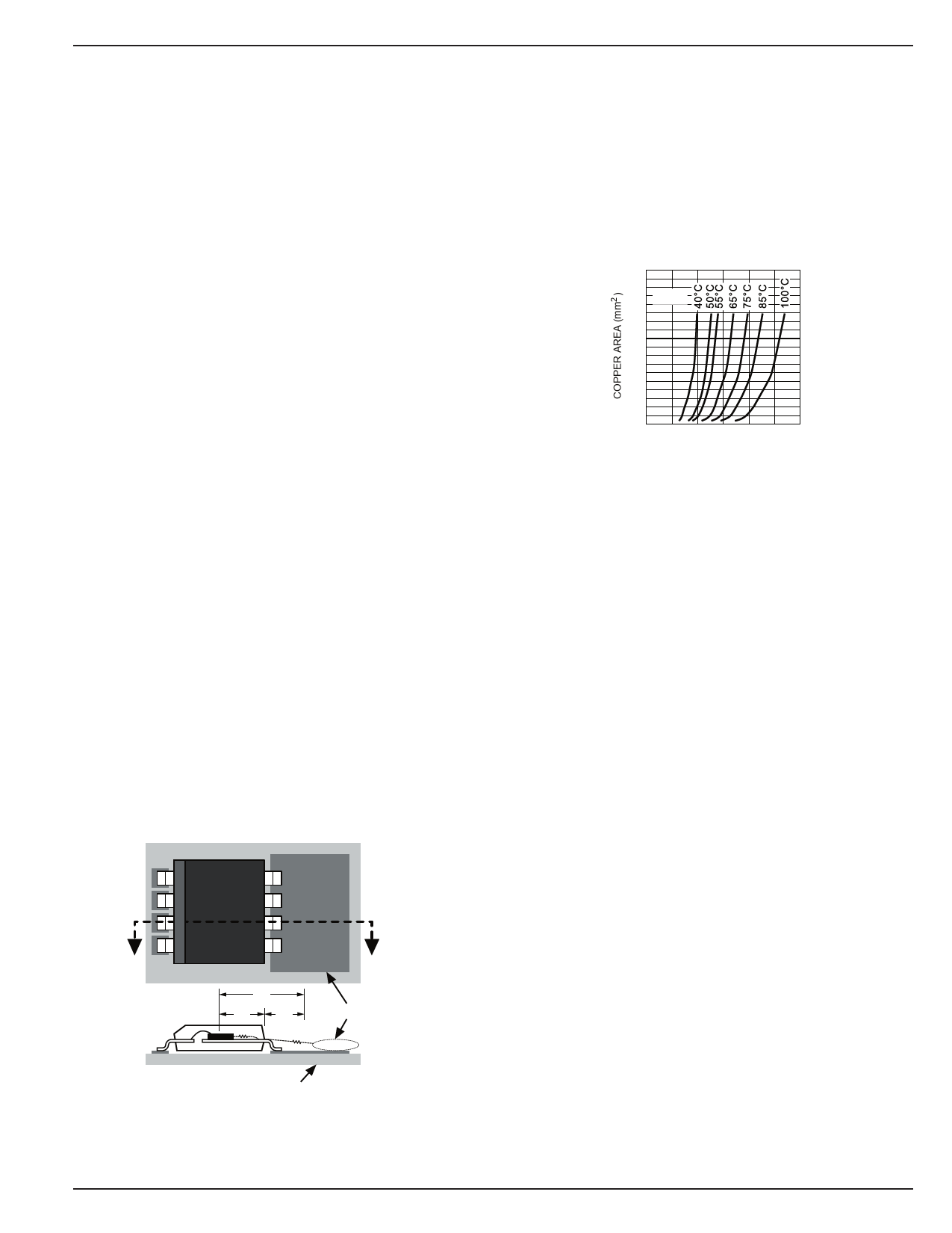
Figure 9 shows curves of copper area versus power dis-
sipation, each trace corresponding to different temperature
rises above ambient. From these curves, the minimum area
of copper necessary for the part to operate safely can be
determined. The maximum allowable temperature rise must
be calculated to determine operation along which curve.
900
800
700 ∆TJ A =
600
500
400
300
200
100
00
0.25 0.50 0.75 1.00 1.25 1.50
POWER DISSIPATION (W)
Figure 9. Copper Area vs. Power-SOIC
Power Dissipation (∆TJA)
Where ΔT = Tj(max) – Ta(max)
Tj(max) = 125°C
Ta(max) = maximum ambient operating
temperature
For example, the maximum ambient temperature is 40°C,
the ΔT is determined as follows:
ΔT = +125°C – 40°C
ΔT = +85°C
Using Figure 9, the minimum amount of required copper can
be determined based on the required power dissipation. Power
dissipation in a linear regulator is calculated as follows:
PD = (Vin-Vout)*Iout + Vin*Ignd
For example, using the charging circuit in Figure 7, assume
the input is a fixed 5V and the output is pulled down to 4.2V
at a charge current of 500mA. The power dissipation in the
MIC79050 is calculated as follows:
PD = (5V – 4.2V)*0.5A + 5V*0.012A
PD = 0.460W
From Figure 9, the minimum amount of copper required to
operate this application at a ΔT of 85C is less than 50mm2.
Quick Method
Determine the power dissipation requirements for the design
along with the maximum ambient temperature at which the
device will be operated. Refer to Figure 10 , which shows
safe operating curves for 3 different ambient temperatures:
+25°C, +50°C and +85°C. From these curves, the minimum
amount of copper can be determined by knowing the maxi-
mum power dissipation required. If the maximum ambient
August 2005
11
MIC79050
Share Link: 