7M0680 データシートの表示(PDF) - Fairchild Semiconductor
部品番号
コンポーネント説明
メーカー
7M0680 Datasheet PDF : 12 Pages
| |||
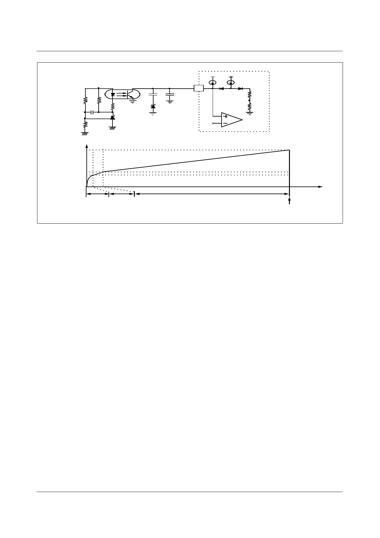
FS7M0880
Vo
K A 431
V fb
C fb
Cd
V z =3.9V
4uA
0.9m A
#4
D1
D2
V fb*
7 .5 V
7.5V
3.9V
3.0V
0V
t1
t2
Tim e Constant
= 3.5R*Cfb
t3
4uA = Cfb*0.9V/t2
4uA = C d*3.6V/t3
t
S h u td o w n
Figure 3. SPS Delayed Shutdown
circuit can perform undesired operations even during
transient state, which lasts until normal operation. As a
measure against this problem, this protection circuit in the
SPS operates after a specified period to determine whether
the condition is a transient or an overload. This is done to
prevent protection circuit operation during a transient state,
which returns normal after a specified period. This operation
is described as follows.
Because the FPS uses the current control mode, it cannot
flow current over the set maximum current, and therefore the
maximum input power is restricted at the characteristic
voltage. Therefore, if the output consumes beyond this
maximum power, VO, shown in the figure below, becomes
less than the set voltage and only the provided minimum
current can flow through KA431. As a result, the secondary
current of the photocoupler becomes almost zero. If all the
SPS’s 0.9mA current source flows through the internal
resistor (2.5R + R ·=· 3k), Vfb becomes approximately 3V,
and the 4µA current starts to charge Cfb. Because the
photocoupler secondary current is almost zero, Vfb
continues to increase until it reaches 7.5V, at which time the
SPS shutsdown. The delay time to shutdown is the time
required to charge Cfb to 4.5V with 4µA and can be easily
set. When Cfb is 10nF(103), t2 is approximately 11.2mS and
when 0.1µF(104) approximately 120ms. With this amount of
the SPS does not shutdown for most transient states. Just
increasing Cfb to obtain a longer delay time can become a
problem, because Cfb is an important parameter for
determining the response speed (Dynamic Response) of the
SMPS. Similarly, Vfb exceeds 3V and the 4uA current starts
to charge the Cfb. At this time, Vfb continues to increase
until it becomes 7.5V, at which time a resistor could be
added between the F/B pin and GND to lengthen the time to
SPS shutdown. If a part of delay current go through the
added resistor, the time to shutdown can be lengthened. In
our test the delay shutdown time with Cfb(473) and resistor
(3.9M) is about two times longer than with only Cfb(473).
When Vfb is 7.5V, the current flowing through this 3.9mΩ
resistor is approximately 1.9µA. To obtain the same results,
if a zener diode (about 3.9 ~ 4.7V) in series connection with
a capacitor is parallel-connected to Cfb, as depicted in Fig 3.,
the desired shutdown delay time could be obtained according
to the size of the capacitor.
Over voltage Protection Circuit
The FPS has a self-protection feature against malfunctions,
such as feedback circuit open or short-circuit. When the
feedback terminal short circuits as seen from the primary
side, the feedback terminal voltage becomes zero, and
switching cannot start as a result. If the feedback terminal
opens, then the protection circuit initiates as in the overload
protection circuit. If the feedback terminal looks open due to
a malfunction in the secondary side feedback circuit or a
non-solder, the primary side continues to switch with the set
maximum current until the protection circuit come on;
therefore, it is normal for the secondary side voltage to
become much greater than the rated voltage. If there was no
protection circuit guarding against such conditions, the fuse
can blow or, even more serious, a fire can start. Even if it
does not lead such dire circumstances, the IC connected to
the secondary side without a regulator could be destroyed
(especially the digital IC such as TTL IC etc.) For such
instances, time, the over voltage protection circuit
(protection against feedback circuit abnormalities) starts to
operate in the SPS. In such circumstances, the output
voltage, which increases tremendously, is made proportional
6
Share Link: 