7M0680 データシートの表示(PDF) - Fairchild Semiconductor
部品番号
コンポーネント説明
メーカー
7M0680 Datasheet PDF : 12 Pages
| |||
to the SPS VCC voltage. If VCC exceeds 24 V, the SPS IC
starts the protection circuit. Therefore, VCC should be
appropriately kept below 24V during normal operation.
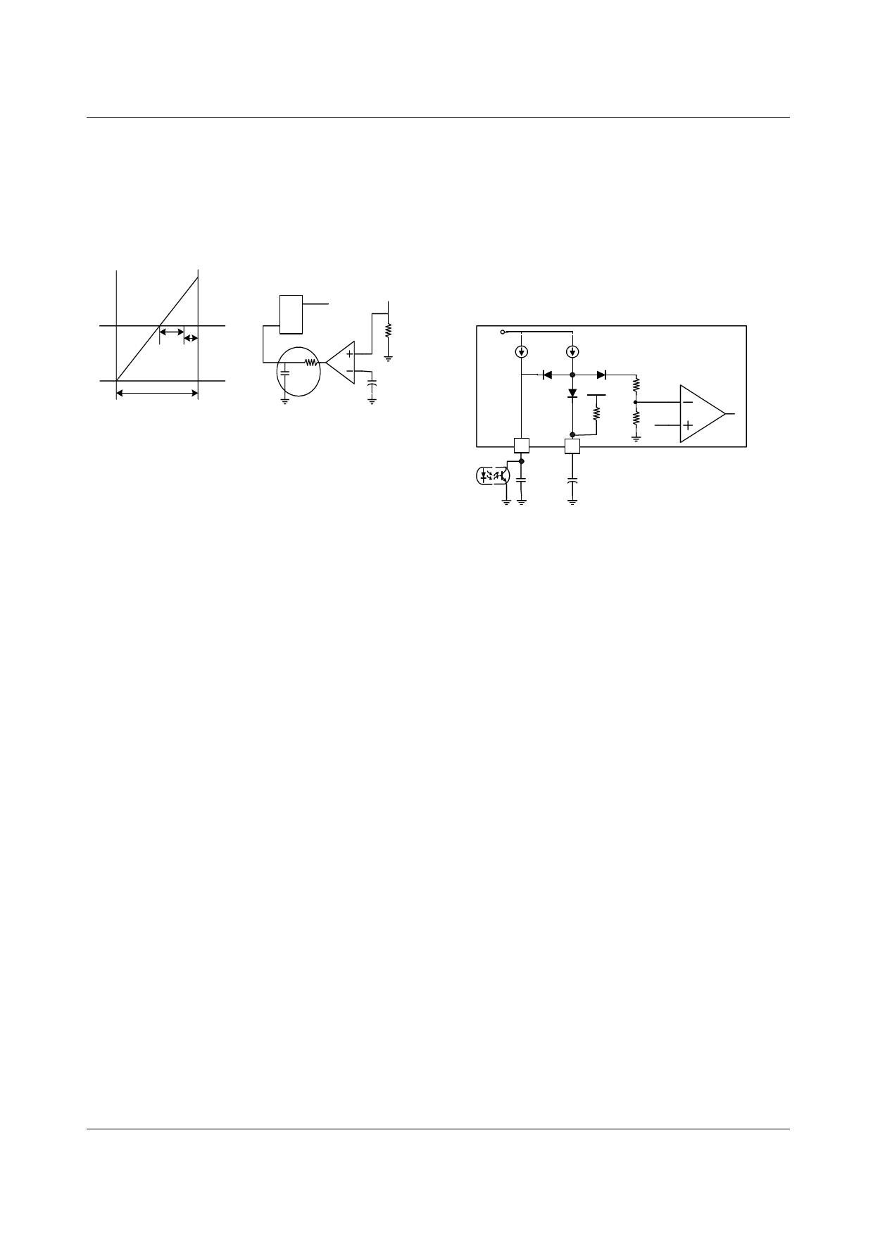
OCP (Over Current Protection)
OCP Operating
200ns
100ns delay
S Q Latch signal
R
OCP time
R
C
Minimum Turn-on Time
Fiqure 5. OCP Function & Block
Rsense
OCP Level
The FPS has various built-in, basic protection features. They
are the UVLO (Under Voltage Lock Out), OLP (Over Load
Protection) and OCP (Over Current Protection). However, if
a secondary side diode short or load short occur due to a
worst case condition, such as a maximum input voltage
putting a large strain on the device, another external
component may need to be added. By adding these
requirements in the FPS, superior reliability and
advantageous cost can be achieved.
When gate on signal of the SenseFet is received,
simultaneously the OCP block senses Ipeak through the
sense resistor for 1us. After the OCP block has turned on,
the voltage across the resistor is compared to the pre-set
voltage in the comparator, and, if it takes longer than 200ns
within the allowed comparison time of 1us, then the
comparator produces a high signal, which latches the OCP.
fig 4. shows the OCP latch waveform. When there is a diode
short/load short, the SPS turns on for the minimum turn-on
time. If the instantaneous current is of the form shown in fig
4., the OCP block opens a 1us window to compare the
voltage proportional to the current across the resistor with
the reference voltage and latches. Here, the 100ns delay
after the 200ns is the delay time to SenseFET gate off and is
generated from the comparison of the voltage across the
sense resistor.
Soft start operation
Normally, the SMPS output voltage increases from start up
with a fixed time constant. This is due to the capacitive
component of the load. At start up, therefore, the feedback
signal applied to the PWM comparator's inverting input
reaches its maximum value (1V), This is because the
feedback loop is effectively open. Also at this time, the
drain current is at its peak value (Ipeak) and maximum
allowable power is being delivered to the secondary load.
With that said, note that when the SMPS pushes maximum
power to the secondary side for this initial fixed time, the
FS7M0880
entire
circuit is seriously stressed. Use of a soft start function
avoids such stresses. Figure 6 shows how to implement a
soft start for a Fairchild Power Switch(FPS). At turn on, the
soft start capacitor on pin 5 of the Fairchild Power
Switch(FPS) starts to charge through the 1mA current
source. When the voltage across CS reaches 3V, diode DS
turns off. No more current flows to it from the 1mA current
source. Cs then continues to charge to 5V through the 20kΩ
resistor.
10V
4uA
0.9mA
Fairchild Power
Switch(FPS)
PWM
Comparator
5V
20K
#4
#5
CS
Figure 6. Soft Start Circuit.
Note that when the voltage across CS exceeds 3V, The voltage
at the comparator’s inverting terminal no longer follows the
voltage across CS. Instead, it follows the output voltage
feedback signal. In shutdown or protection circuit operation,
capacitor CS is discharged, to enable it to charge from 0V at
restart.
7
Share Link: 