AD592(RevA) データシートの表示(PDF) - Analog Devices
部品番号
コンポーネント説明
メーカー
AD592 Datasheet PDF : 8 Pages
| |||
AD592
The circuit shown can be optimized for any ambient tempera-
ture range or thermocouple type by simply selecting the correct
value for the scaling resistor – R. The AD592 output (1 µA/K)
times R should approximate the line best fit to the thermocouple
curve (slope in V/°C) over the most likely ambient temperature
range. Additionally, the output sensitivity can be chosen by
selecting the resistors RG1 and RG2 for the desired noninverting
gain. The offset adjustment shown simply references the AD592
to °C. Note that the TC’s of the reference and the resistors are
the primary contributors to error. Temperature rejection of 40
to 1 can be easily achieved using the above technique.
Although the AD592 offers a noise immune current output, it is
not compatible with process control/industrial automation cur-
rent loop standards. Figure 12 is an example of a temperature to
4–20 mA transmitter for use with 40 V, 1 kΩ systems.
In this circuit the 1 µA/K output of the AD592 is amplified to
1 mA/°C and offset so that 4 mA is equivalent to 17°C and
20 mA is equivalent to 33°C. Rt is trimmed for proper reading
at an intermediate reference temperature. With a suitable choice
of resistors, any temperature range within the operating limits of
the AD592 may be chosen.
AD581
AD592
35.7kΩ
10mV/oC RT
5kΩ
17°C ≈ 4mA
33°C ≈ 20µA
1mA/oC
+20V
208
C
10kΩ 12.7kΩ
5kΩ 500Ω
10Ω
VT
–20V
Figure 12. Temperature to 4–20 mA Current Transmitter
Reading temperature with an AD592 in a microprocessor based
system can be implemented with the circuit shown in Figure 13.
+5V
AD592
SPAN
TRIM
100Ω
950Ω
AD1403
9kΩ
200Ω
CENTER
POINT
TRIM
1kΩ
BPO/UPO
FORMAT
VCC
VI N HI
AD670
VIN LO ADCPORT
8 BITS
OUT
VIN HI
VI N LO
GND
R/W CS
CE
µP CONTROL
Figure 13. Temperature to Digital Output
By using a differential input A/D converter and choosing the
current to voltage conversion resistor correctly, any range of
temperatures (up to the 130°C span the AD592 is rated for)
centered at any point can be measured using a minimal number
of components. In this configuration the system will resolve up
to 1°C.
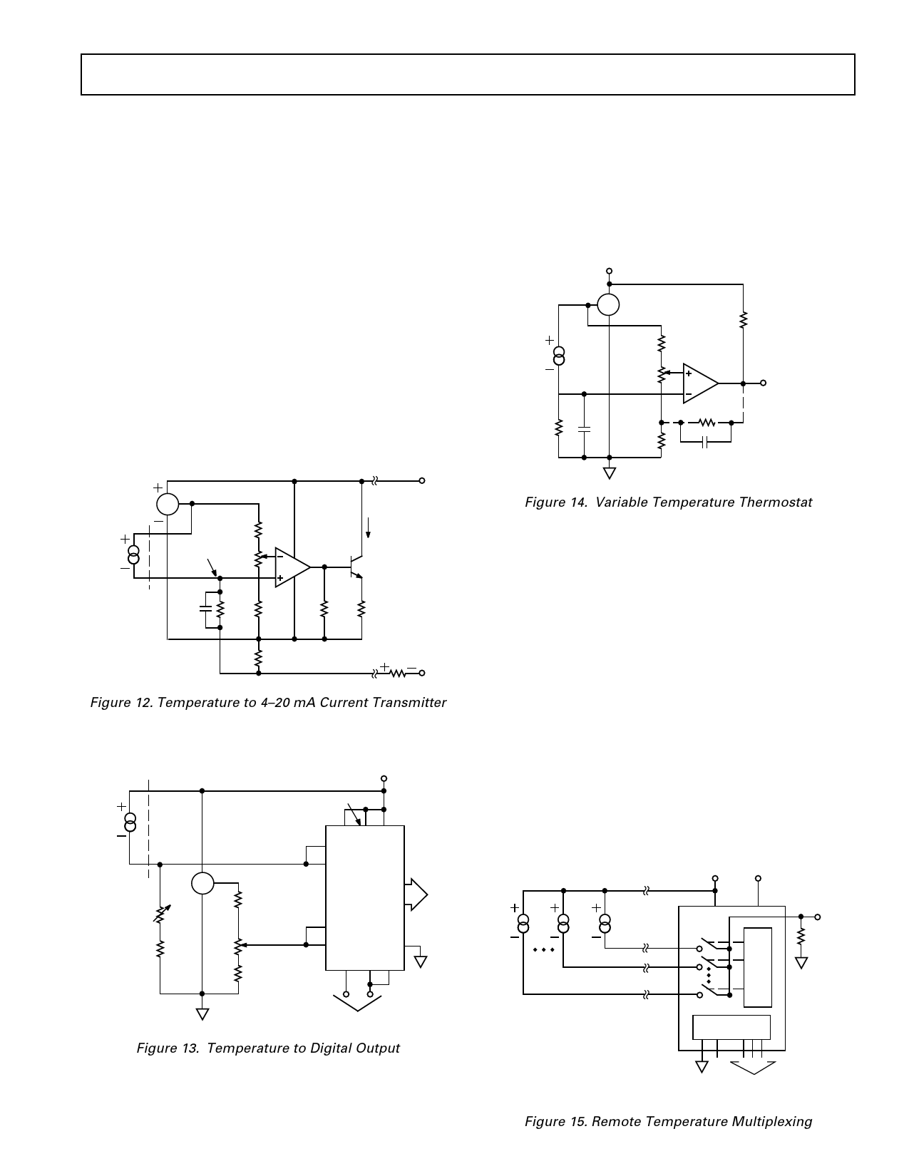
A variable temperature controlling thermostat can easily be built
using the AD592 in the circuit of Figure 14.
+15V
AD592
10kΩ
AD581
RHIGH
62.7kΩ
RSET
10kΩ
RPULL-UP
COMPARATOR
TEMP > SETPOINT
OUTPUT HIGH
RHYST
TEMP < SETPOINT
OUTPUT LOW
C
RLOW
27.3kΩ
(OPTIONAL)
C
Figure 14. Variable Temperature Thermostat
RHIGH and RLOW determine the limits of temperature controlled
by the potentiometer RSET. The circuit shown operates over the
full temperature range (–25°C to +105°C) the AD592 is rated
for. The reference maintains a constant set point voltage and
insures that approximately 7 V appears across the sensor. If it is
necessary to guardband for extraneous noise hysteresis can be
added by tying a resistor from the output to the ungrounded
end of RLOW.
Multiple remote temperatures can be measured using several
AD592s with a CMOS multiplexer or a series of 5 V logic gates
because of the device’s current-mode output and supply-voltage
compliance range. The on-resistance of a FET switch or output
impedance of a gate will not affect the accuracy, as long as 4 V
is maintained across the transducer. MUXs and logic driving
circuits should be chosen to minimize leakage current related
errors. Figure 15 illustrates a locally controlled MUX switching
the signal current from several remote AD592s. CMOS or TTL
gates can also be used to switch the AD592 supply voltages,
with the multiplexed signal being transmitted over a single
twisted pair to the load.
+15V
–15V
T8
T2
T1
REMOTE
AD592s
AD7501
D
S1
ED
CR
S2
OI
DV
EE
S8
RR
/
TTL DTL TO
CMOS I/O
VOUT
10kΩ
EN
CHANNEL
SELECT
REV. A
Figure 15. Remote Temperature Multiplexing
–7–
Share Link: 