DS2430A(2012) データシートの表示(PDF) - Maxim Integrated
部品番号
コンポーネント説明
メーカー
DS2430A Datasheet PDF : 19 Pages
| |||
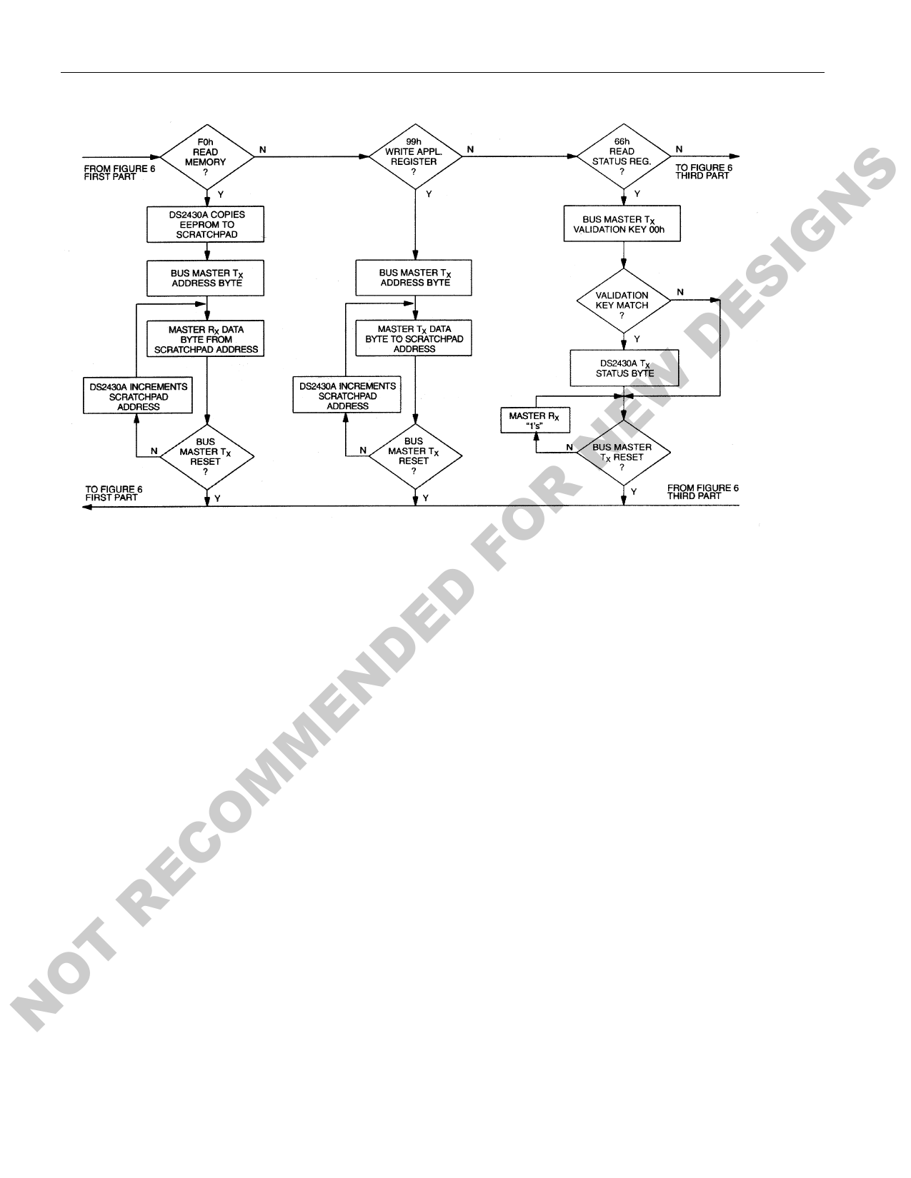
MEMORY FUNCTION FLOW CHART Figure 6 (continued)
DS2430A
DESIGNS
NEW
FOR WRITE APPLICATION REGISTER [99h]
This command is essentially the same as the Write Scratchpad command, but it addresses the 64-bit
D register scratchpad. After issuing the command code, the master must provide a 1-byte address, followed
by the data to be written. The DS2430A automatically increments the address after every byte it receives.
E After receiving the data byte for address 07h, the address counter wraps around to 00h for the next byte
D and writing continues until the master sends a Reset Pulse. The Write Application Register command can
N be used as long as the application register has not yet been locked. If issued for a device with the
application register locked, the data written to the register scratchpad will be lost.
ME READ STATUS REGISTER [66h]
The status register is a means for the master to find out whether the application register has been
M programmed and locked. After issuing the read status register command, the master must provide the
validation key 00h before receiving status information. The two least significant bits of the 8-bit status
O register are 0 if the application register was programmed and locked; all other bits always read 1. The
REC master may finish the read status command by sending a Reset Pulse at any time.
NOT
7 of 19
Share Link: 