TIP31C データシートの表示(PDF) - Diotec Semiconductor Germany
部品番号
コンポーネント説明
メーカー
TIP31C Datasheet PDF : 2 Pages
| |||
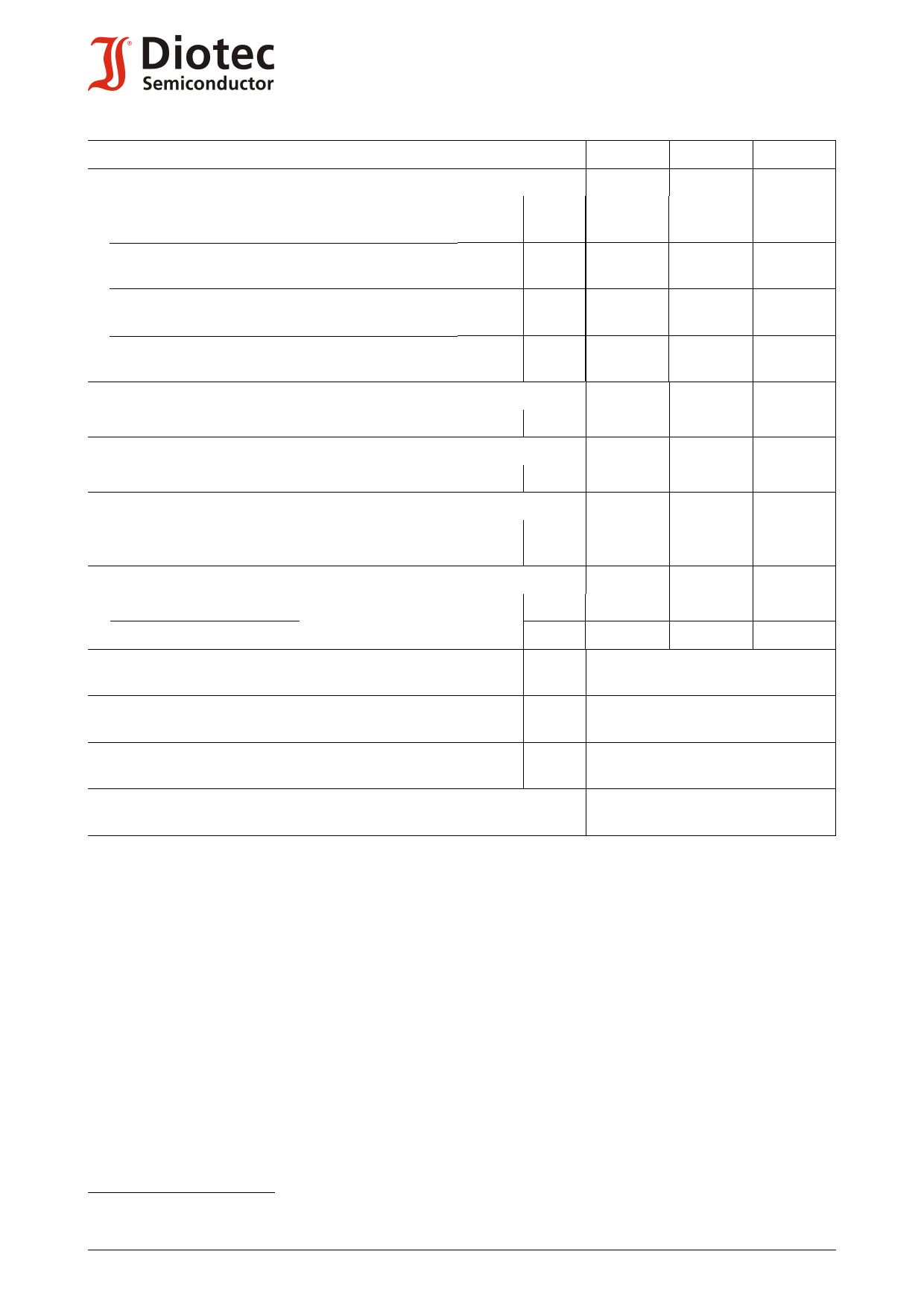
Characteristics (Tj = 25°C)
Collector-Emitter cutoff current – Kollektor-Emitter-Reststrom
VCE = 30 V (B open)
TIP31
ICE0
TIP31A ICE0
VCE = 60 V (B open)
TIP31B ICE0
TIP31C ICE0
VCE = 40 V (B-E short)
VCE = 60 V (B-E short)
TIP31
ICES
TIP31A ICES
VCE = 80 V (B-E short)
VCE = 100 V (B-E short)
TIP31B ICES
TIP31C ICES
Emitter-Base cutoff current
VEB = 5 V, (C open)
IEB0
Gain-Bandwidth Product – Transitfrequenz
VCE = 10 V, IC = 0.5 A, f = 1 MHz
fT
Small signal current gain – Kleinsignal-Stromverstärkung
VCE = 10 V, IC = 0.5 A, f = 1 kHz
hfe
VCE = 10 V, IC = 0.5 A, f = 1 MHz
hfe
Switching times – Schaltzeiten (between 10% and 90% levels)
turn-on time
turn-off time
ICon = 1 A
ton
IBon = - IBoff = 100 mA
toff
Thermal resistance junction to ambient air
Wärmewiderstand Sperrschicht – umgebende Luft
RthA
Thermal resistance junction to case
Wärmewiderstand Sperrschicht – Gehäuse
RthC
Admissible torque for mounting
Zulässiges Anzugsdrehmoment
M4
Recommended complementary PNP transistors
Empfohlene komplementäre PNP-Transistoren
TIP31 ... TIP31C
Kennwerte (Tj = 25°C)
Min.
Typ.
Max.
–
–
300 nA
–
–
300 nA
–
–
300 nA
–
–
300 nA
–
–
200 nA
–
–
200 nA
–
–
200 nA
–
–
200 nA
–
–
1 mA
3 MHz
–
–
20
–
–
3
–
–
–
300 ns
–
–
1 µs
–
< 63 K/W 1)
< 3 K/W
9 ± 10% lb.in.
1 ± 10% Nm
TIP32 ... TIP32C
1 Valid, if leads are kept at ambient temperature at a distance of 5 mm from case
Gültig wenn die Anschlussdrähte in 5 mm Abstand vom Gehäuse auf Umgebungstemperatur gehalten werden
2
http://www.diotec.com/
© Diotec Semiconductor AG
Share Link: 