LP28300 データシートの表示(PDF) - Unspecified
部品番号
コンポーネント説明
メーカー
LP28300 Datasheet PDF : 10 Pages
| |||
Preliminary Datasheet
LP28300
Operation
The LP28300 is a constant current, constant voltage
Li-Ion battery charger controller that uses a current
mode PWM step-down (buck) switching
architecture. The charge current is set by an external
sense resistor (RSENSE) across the SENSE and BAT
pins. The final battery float voltage is internally set
to 4.2V per cell. For batteries like lithium-ion that
require accurate final float voltage, the internal 2.4V
reference, voltage amplifier and the resistor divider
provide regulation with ±1% accuracy.
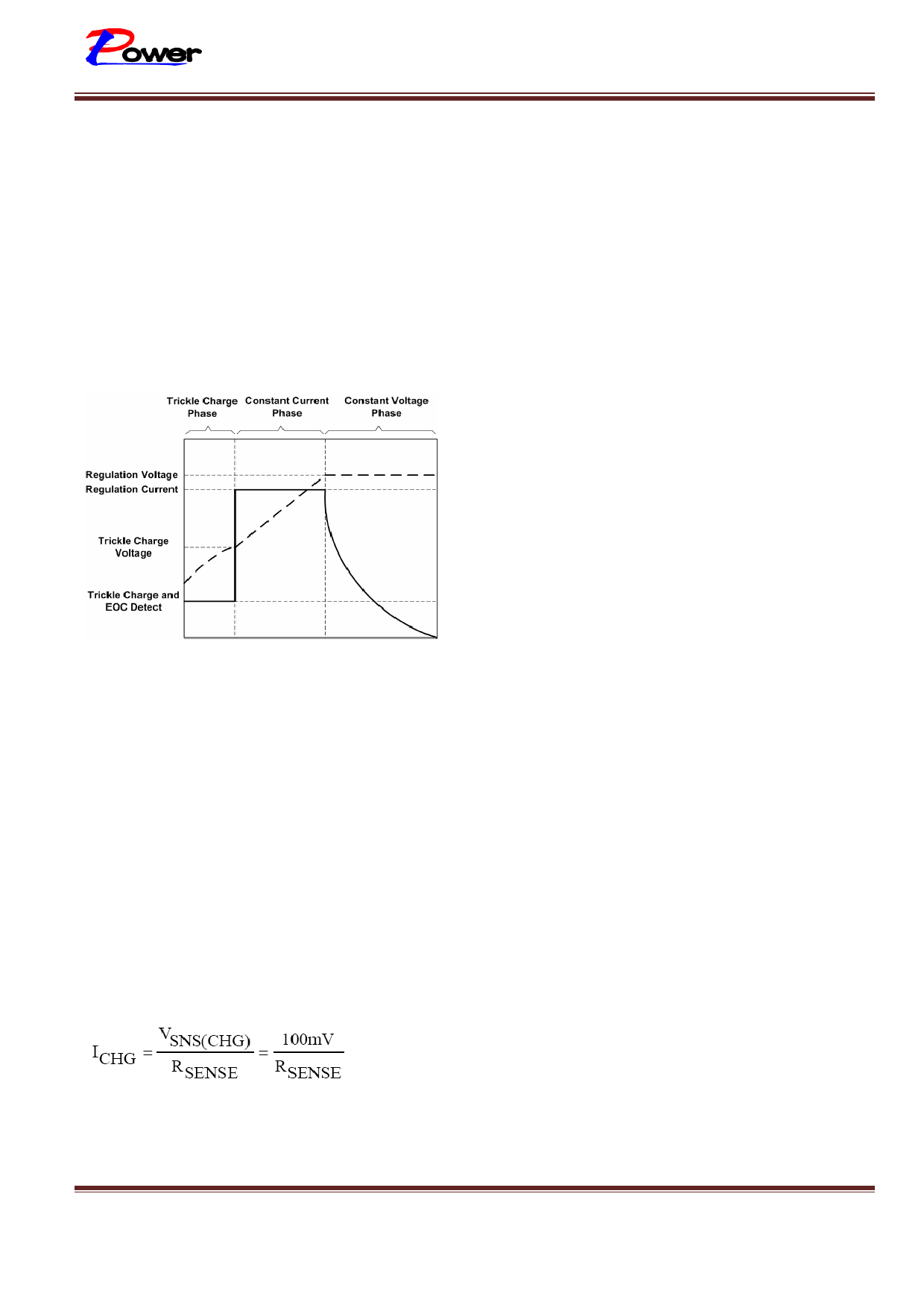
Figure 1.Typical Charge Profile
start to decrease. When the current drops to 25%
of the full-scale charge current, an internal
comparator turns off the internal pull-down
N-channel MOSFET at the STAT pin, and connects
a weak current source to ground to indicate a near
end-of-charge condition. A 10kΩ NTC (negative
temperature coefficient) thermistor can be
connected from the NTC pin to ground for battery
temperature qualification. The charge cycle is
suspended when the temperature is outside of the
0°C to 50°C window.
Shutdown
The LP28300 can be shut down by pulling the
COMP pin to ground which pulls the GATE pin
high turning off the external P-channel MOSFET.
When the COMP pin is released, the internal timer
is reset and a new charge cycle starts. In shutdown,
the output of the CHRG pin is high impedance and
the quiescent current remains at 1.5mA. Removing
the input power supply will put the charger into
sleep mode. If the voltage at the VCC pin drops
below (VBAT + 250mV) or below the UVLO level,
the LP28300 goes into a low current (ICC = 10µA)
sleep mode, reducing the battery drain current.
A charge cycle begins when the voltage at the VCC
pin rises above the UVLO level and is 250mV or
more greater than the battery voltage. At the
beginning of the charge cycle, if the battery voltage
is less than the trickle charge threshold, 2.9V for the
4.2 version, the charger goes into trickle charge
mode. The trickle charge current is internally set to
15% of the full-scale current. If the battery voltage
stays low for 30 minutes, the battery is considered
faulty and the charge cycle is terminated. When the
battery voltage exceeds the trickle charge threshold,
the charger goes into the full-scale constant current
charge mode. In constant current mode, the charge
current is set by the external sense resistor RSENSE
and an internal 100mV reference;
When the battery voltage approaches the
programmed float voltage, the charge current will
Automatic Recharge
Once the charge cycle is terminated, the LP28300
continuously monitors the voltage on the BAT pin
using a comparator with a 2ms filter time
(tRECHARGE). A charge cycle restarts when the battery
voltage falls below 4.05V (which corresponds to
approximately 80% to 90% battery capacity). This
ensures that the battery is kept at or near a fully
charged condition and eliminates the need for
periodic charge cycle initiations. STAT output enters
a strong pull-down state during recharge cycles.
Battery Temperature Detection
A negative temperature coefficient (NTC)
thermistor located close to the battery pack can be
used to monitor battery temperature and will not
allow charging unless the battery temperature is
within an acceptable range. Connect a 10kΩ
thermistor from the TS pin to ground. If the
LP28300 – 01 Version 1.1 Datasheet
Sep.-2010
www.lowpowersemi.com
Page 7 of 10
Share Link: 