LP28300 データシートの表示(PDF) - Unspecified
部品番号
コンポーネント説明
メーカー
LP28300 Datasheet PDF : 10 Pages
| |||
Preliminary Datasheet
LP28300
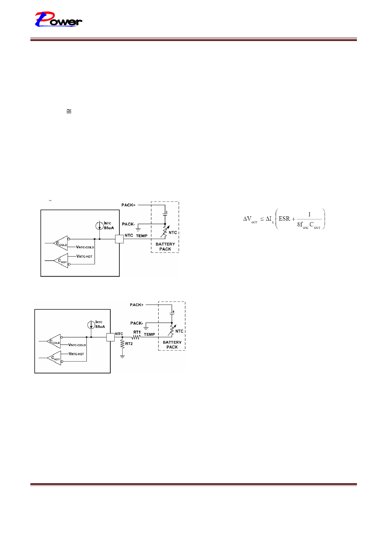
temperature rises to 50°C, the resistance of the
one-half of output charge current. Actual
NTC will be approximately 4.2kΩ. With the 85µA
pull-up current source, the Hot temperature
voltage threshold is 360mV. For Cold temperature,
the voltage threshold is set at 2.4V which is equal
to 0°C (Rts 28kΩ) with 85µA of pull-up current.
If the temperature is outside the window, the
GATE pin will be pulled up to VCC and the timer
frozen while the output status at the STAT pin
remains the same. The charge cycle begins or
resumes once the temperature is within the
acceptable range. Short the TS pin to ground to
disable the temperature qualification feature.
However the user may modify these thresholds by
adding two external resistor. See figure 3.
capacitance value is not critical. Solid tantalum
capacitors have a high ripple current rating in a
relatively small surface mount package, but
caution must be used when tantalum capacitors
are used for input bypass. High input surge
currents can be created when the adapter is
hot-plugged to the charger and solid tantalum
capacitors have a known failure mechanism when
subjected to very high turn-on surge currents.
Selecting the highest possible voltage rating on
the capacitor will minimize problems. Consult
with the manufacturer before use. The selection
of output capacitor COUT is primarily determined
by the ESR required to minimize ripple voltage
and load step transients. The output ripple ∆VOUT
is approximately bounded by:
Figure 2. Temperature Sensing Configuration
Figure 3. Temperature Sensing Thresholds
Since ∆IL increases with input voltage, the output
ripple is highest at maximum input voltage.
Typically, once the ESR requirement is satisfied,
the capacitance is adequate for filtering and has
the necessary RMS current rating. Switching
ripple current splits between the battery and the
output capacitor depending on the ESR of the
output capacitor and the battery impedance. EMI
considerations usually make it desirable to
minimize ripple current in the battery leads.
Ferrite beads or an inductor may be added to
increase battery impedance at the 500kHz
switching frequency. If the ESR of the output
capacitor is 0.2Ω and the battery impedance is
raised to 4Ω with a bead or inductor, only 5% of
the current ripple will flow in the battery.
Input and Output Capacitors
Since the input capacitor is assumed to absorb all
input switching ripple current in the converter, it
must have an adequate ripple current rating.
Worst-case RMS ripple current is approximately
LP28300 – 01 Version 1.1 Datasheet
Sep.-2010
Inductor Selection
A high (1.5MHz) operating frequency was chosen
for the buck switcher in order to minimize the size
of the inductor. However, take care to use inductors
with low core losses at this frequency. A good
www.lowpowersemi.com
Page 8 of 10
Share Link: 