LP28300 データシートの表示(PDF) - Unspecified
部品番号
コンポーネント説明
メーカー
LP28300 Datasheet PDF : 10 Pages
| |||
Preliminary Datasheet
LP28300
choice is the IHLP-2525AH-01from Vishay Dale.
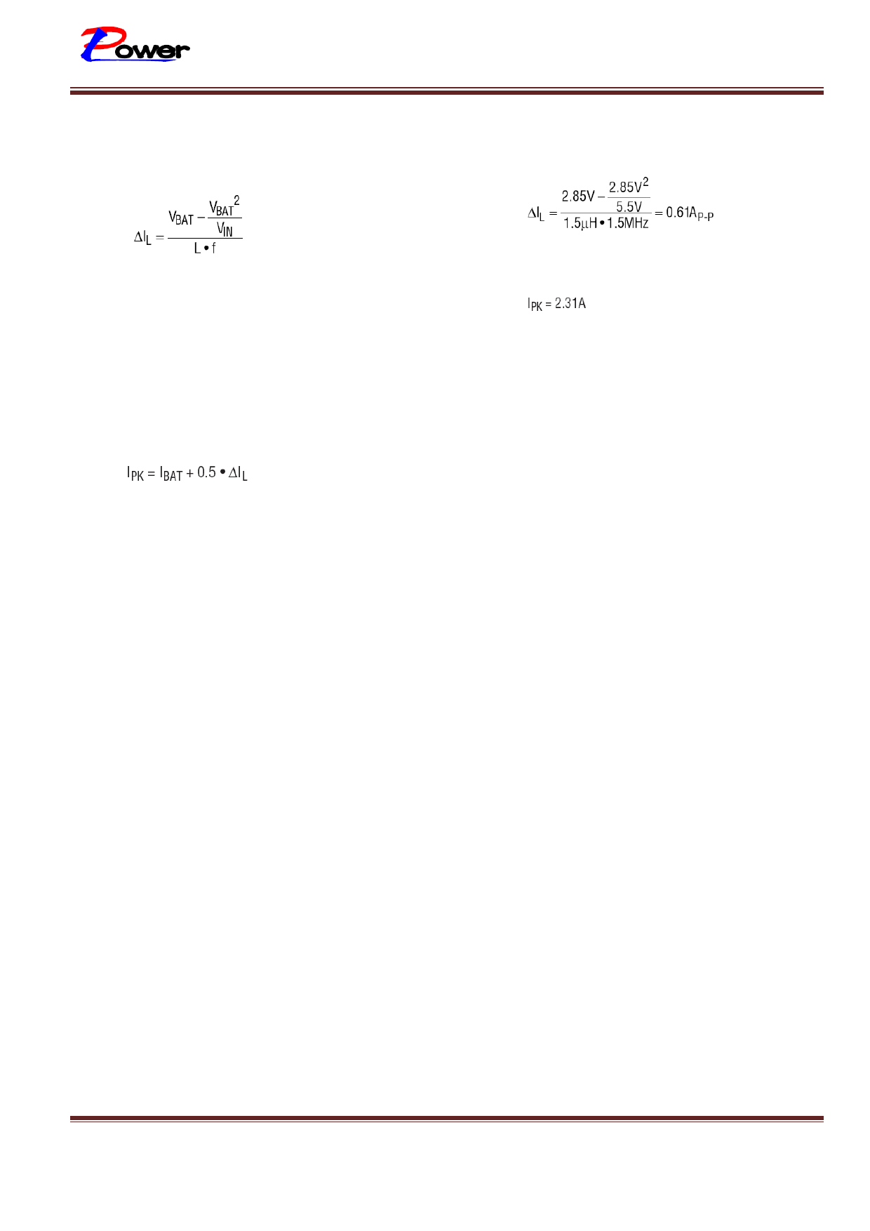
To calculate the inductor ripple current:
typical application. With 1.5µH and2A charge
current:
and
where VBAT is the battery voltage, VIN is the input
voltage, L is the inductance and f is the PWM
oscillator frequency(typically 1.5MHz). Maximum
inductor ripple current occurs at maximum VIN and
VBAT = VIN/2.
Peak inductor current will be:
where IBAT is the maximum battery charging
current.
When sizing the inductor make sure that the peak
current will not exceed the saturation current of the
inductors. Also, ∆IL should never exceed 0.4(IBAT)
as this may interfere with proper operation of the
output short-circuit protection comparator. 1.5µH
provides reasonable inductor ripple current in a
Layout Considerations
Switch rise and fall times are kept under 5ns for
maximum efficiency. To minimize radiation, the SW
pin and input bypass capacitor leads (between VIN
and PGND) should be kept as short as possible. A
ground plane should be used under the switching
circuitry to prevent inter plane coupling. The
exposed pad must be connected to the ground plane
for proper power dissipation. The other paths
contain only DC and/or 1.5MHz tri-wave ripple
current and are less critical. With the exception of
the input and output filter capacitors(which should
be connected to PGND) all other components that
return to ground should be connected to GND.
LP28300 – 01 Version 1.1 Datasheet
Sep.-2010
www.lowpowersemi.com
Page 9 of 10
Share Link: 