PD69100 データシートの表示(PDF) - Microsemi Corporation
部品番号
コンポーネント説明
メーカー
PD69100 Datasheet PDF : 5 Pages
| |||
PD69100
TM
®
PoE Controller Unit
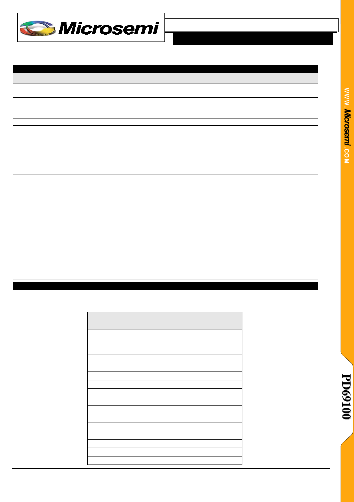
Function
Supports up to eight PoE
devices – 96 ports
Power Management
Threshold Configuration
High power ports, 2 pairs
or 4 pairs
Communication
Legacy (capacitor)
Detection
LED Stream
System OK Indication
System and Port
Measurements
Detailed Port Status
Interrupt Pin
Port Power Limit
Port Matrix Control
‘Power Good’ Interrupt
from Power Supply
Directly to POE Drivers.
DATASHEET
MAIN FEATURES DESCRIPTION
Description
Up to 12 PoE devices can be cascaded, fitting into a 96 port PoE system that
utilizes one PoE controller (PD69100)
The system supports three power management modes: Class (LLDP) mode,
Dynamic mode and Static mode. For more details see technical note 113, catalogue
number 06-0002-081.
Configure overvoltage and under-voltage thresholds for disconnection purposes.
PoE devices can be configured (both hardware and software) to enable higher
current through ports (up to ~720mA) or double power RJ in case of 4 pairs.
Supports both I2C and UART interfaces with Host CPU.
Enables detection and powering of pre-standard devices (PDs).
Direct SPI interface to an external LED stream circuitry. Enables designers to
implement a simple LED circuit that does not require a software code.
Digital output pin to Host, indicating voltage and temperature range are valid.
Measurements of the following parameters: Current (mA), Power Consumption (W),
Vmain (V), Port Voltage (V), PD Class (0-4).
Port statuses are received from PoE managers. Statuses such as ‘port on’ and ‘port
off due to disconnection or due to overload’
Interrupt out from PoE controller indicating events such as: port on, port off, port
fault, PoE device fault, voltage out of range, and more. For a full list of interrupt
events refer to Serial Communication Protocol, catalogue number 06-0032-056.
Configurable port power limit; when a port exceeds the limit, it is automatically
disconnected
Enables layout designers to connect all physical ports to logical ports whenever
required.
For systems comprising more than a single power supply, in case one power supply
fails, a fast port disconnection mechanism is executed to maintain operation and
prevent collapse of other power supplies.
I2C ADDRESS SELECTION
I2C interface between Host CPU and a specific PD69000 requires setting the device address; this is done by
applying a specific voltage level to pin #25 (I2C_ADDR) as shown below:
I2C_ADDR
VOLTAGE LEVEL
0.00 to 0.21VDC
0.21 to 0.41VDC
0.41 to 0.62VDC
0.62 to 0.83VDC
0.83 to 1.03VDC
1.03 to 1.24VDC
1.24 to 1.44VDC
1.44 to 1.65VDC
1.65 to 1.86VDC
1.86 to 2.06VDC
2.06 to 2.27VDC
2.27 to 2.48VDC
2.48 to 2.68VDC
2.68 to 2.89VDC
2.89 to 3.09VDC
3.09 to 3.30VDC
I2C ADDRESS
(HEXADECIMAL)
UART
0x4
0x8
0xC
0x10
0x14
0x18
0x1C
0x20
0x24
0x28
0x2C
0x30
0x34
0x38
0x3C
Copyright © 2010
Microsemi
3
Rev. 1.1, Dec. 2010
Analog Mixed Signal Group
2381 Morse Avenue, Irvine, CA 92614, USA; Within the USA: (800) 713-4113, Outside the USA: (949) 221-7100 Fax: (949) 756-0308
Share Link: 