BD6757KN データシートの表示(PDF) - ROHM Semiconductor
部品番号
コンポーネント説明
メーカー
BD6757KN
ROHM Semiconductor

BD6757KN Datasheet PDF : 16 Pages
| |||
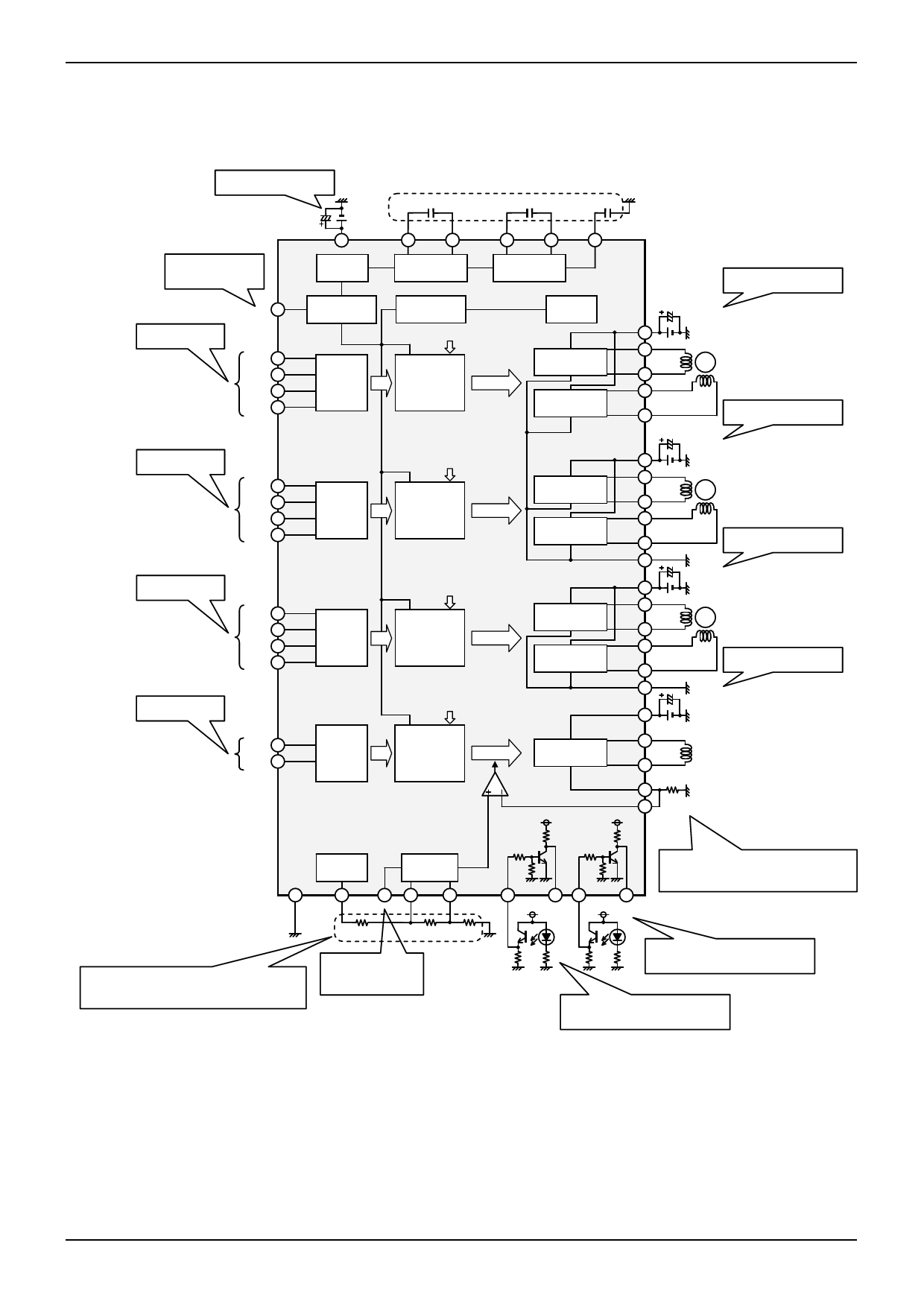
BD6757KN, BD6889GU
●Application Circuit Diagram
Technical Note
Bypass filter Capacitor for
power supply input. (p.14/16)
Power-saving (p.9/16)
H : Active
L : Standby
1~100uF
VCC
9
OSC
Motor control input
(p.9/16)
PS 11
Power Save
IN1A 25
IN1B 26
IN2A 27
IN2B 28
Logic12
Motor control input
(p.9/16)
IN3A 29
IN3B 37
IN4A 38
IN4B 39
Motor control input
(p.9/16)
Motor control input
(p.9/16)
IN5A 15
IN5B 14
IN6A 13
IN6B 12
IN7A 3
IN7B 1
Logic34
Logic56
Logic7
0.1μF
CP1
31
CP2
32
Charge Pump
TSD & UVLO
VG
Level Shift
&
Pre Driver
VG
Level Shift
&
Pre Driver
VG
Level Shift
&
Pre Driver
VG
Level Shift
&
Pre Driver
0.1μF
0.1μF
CP3
33
CP4
34
VG
35
Charge Pump
BandGap
H bridge
Full ON
H bridge
Full ON
Bypass filter Capacitor for
power supply input. (p.14/16)
1~100uF
10
VM1
16
OUT1A
M
17 OUT1B
18 OUT2A
19 OUT2B
Bypass filter Capacitor for
power supply input. (p.14/16)
H bridge
Full ON
H bridge
Full ON
H bridge
Full ON
H bridge
Full ON
H bridge
Const. Current
VCC
1~100uF
30
VM2
22
OUT3A
M
21 OUT3B
24 OUT4A
23 OUT4B
20 PGND1
1~100uF
36
VM3
42
OUT5A
M
43 OUT5B
45 OUT6A
46 OUT6B
44 PGND2
1~100uF
2
VM4
47 OUT7A
49 OUT7B
RNF
48
50 0.1Ω~5.0Ω
SENSE
VCC
Bypass filter Capacitor for
power supply input. (p.14/16)
Bypass filter Capacitor for
power supply input. (p.14/16)
VREF
Selector
4
GND
5
8
VREF LIMSW
R1
6
7
VLIMH VLIML
40
SI1
R2
R3
When using the VREF voltage (0.9V) resistance division
value as VLIMH and VLIML input value, select R1, R2, and R3
values such that,
1kΩ≦R1+R2+R3≦20kΩ (p.9/16)
Output current selection
(p.9/16)
H : VLIML
L : VLIMH
52 41
SO1 SI2
51
SO2
The output current is converted to a voltage with
the RNF external resistor and transmitted to the
SENSE pin. (p.9/16)
Iout[A] = (VLIMH or VLIML[V])÷RNF[Ω]
The sensor signal SI2, for lens position
detection, is reshaped and output to SO2.
p.10/16
The sensor signal SI1, for lens position
detection, is reshaped and output to SO1.
p.10/16
Fig.12 BD6757KN Application Circuit Diagram
www.rohm.com
© 2009 ROHM Co., Ltd. All rights reserved.
7/15
2009.06 - Rev.A
Share Link: