AN826 „Éá„Éľ„āŅ„ā∑„Éľ„Éą„ĀģŤ°®Á§ļÔľąPDFÔľČ - Microchip Technology
ťÉ®ŚďĀÁē™ŚŹ∑
„ā≥„É≥„ÉĚ„Éľ„Éć„É≥„ÉąŤ™¨śėé
„É°„Éľ„āę„Éľ
AN826
Microchip Technology

AN826 Datasheet PDF : 14 Pages
| |||
AN826
unique in that the impedance of the crystal changes so
rapidly with frequency that all other circuit components
can be considered to be of constant reactance, this
reactance being calculated at the nominal frequency of
the crystal. The frequency of oscillation will adjust itself
so that the crystal presents a reactance to the circuit
which will satisfy the Barkhausen phase requirement
[5].
Figure 12 again shows a simplified oscillator circuit
drawn with only the RF components, no biasing resis-
tors, and no ground connection [3]. The inductor has
been replaced by a crystal. We shall see for the Pierce
and Colpitts crystal oscillators, the crystal will appear
inductive in the circuit in order to oscillate.
FIGURE 12: SIMPLIFIED CRYSTAL
OSCILLATOR CIRCUIT
WITHOUT RF GROUND
frequency of the crystal, it poses more or less phase
shift such that the total is not equal to 360 degrees.
Therefore, steady-state operation is maintained at the
crystal frequency. However, this only happens in an
ideal circuit.
FIGURE 14: PIERCE CRYSTAL
OSCILLATOR, IDEAL
OPERATION [6]
Pierce Crystal Oscillator
The Pierce crystal oscillator (Figure 13) is a series res-
onant circuit for Fundamental mode crystals. It oscil-
lates just above the series resonant frequency of the
crystal [3]. The Pierce oscillator is designed to look into
the lowest possible impedance across the crystal termi-
nals [6].
FIGURE 13: PIERCE CRYSTAL OSCILLATOR
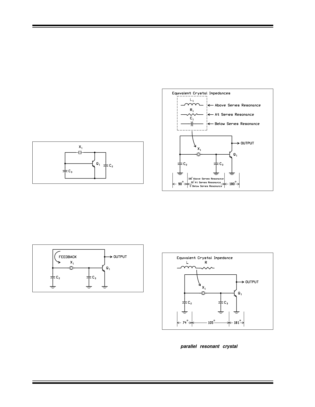
In actual circuit operation (Figure 15), the phase shift
through the transistor is typically more than 180
degrees because of increased delay and the tuned cir-
cuit typically falls short of 180 degrees. Therefore the
crystal must appear inductive to provide the phase shift
needed in the circuit to sustain oscillation.
FIGURE 15: PIERCE CRYSTAL
OSCILLATOR, ACTUAL
OPERATION [6]
In the Pierce oscillator, the ground point location has a
profound effect on the performance. Large phase shifts
in RC networks and large shunt capacitances to ground
on both sides of the crystal make the oscillation fre-
quency relatively insensitive to small changes in series
resistances or shunt capacitances. In addition, RC roll-
off networks and shunt capacitances to ground mini-
mize any transient noise spikes which give the circuit a
high immunity to noise [6].
At series resonance, the crystal appears resistive in
the circuit (Figure 14) and the phase shift around the
circuit is 2ŌÄ radians (360 degrees). If the frequency of
the circuit shifts above or below the series resonant
DS00826A-page 8
Thus the output frequency of the Pierce crystal oscilla-
tor is not at the crystal series resonant frequency. Typi-
cally a parallel resonant crystal is specified by
frequency and load capacitance (CL). CL is the circuit
capacitance the crystal expects to see and operate at
the desired frequency. The circuit load capacitance is
determined by external capacitors C2 and C3, transistor
© 2002 Microchip Technology Inc.
Share Link: