AN826 データシートの表示(PDF) - STMicroelectronics
部品番号
コンポーネント説明
メーカー
AN826 Datasheet PDF : 7 Pages
| |||
APPLICATION NOTE
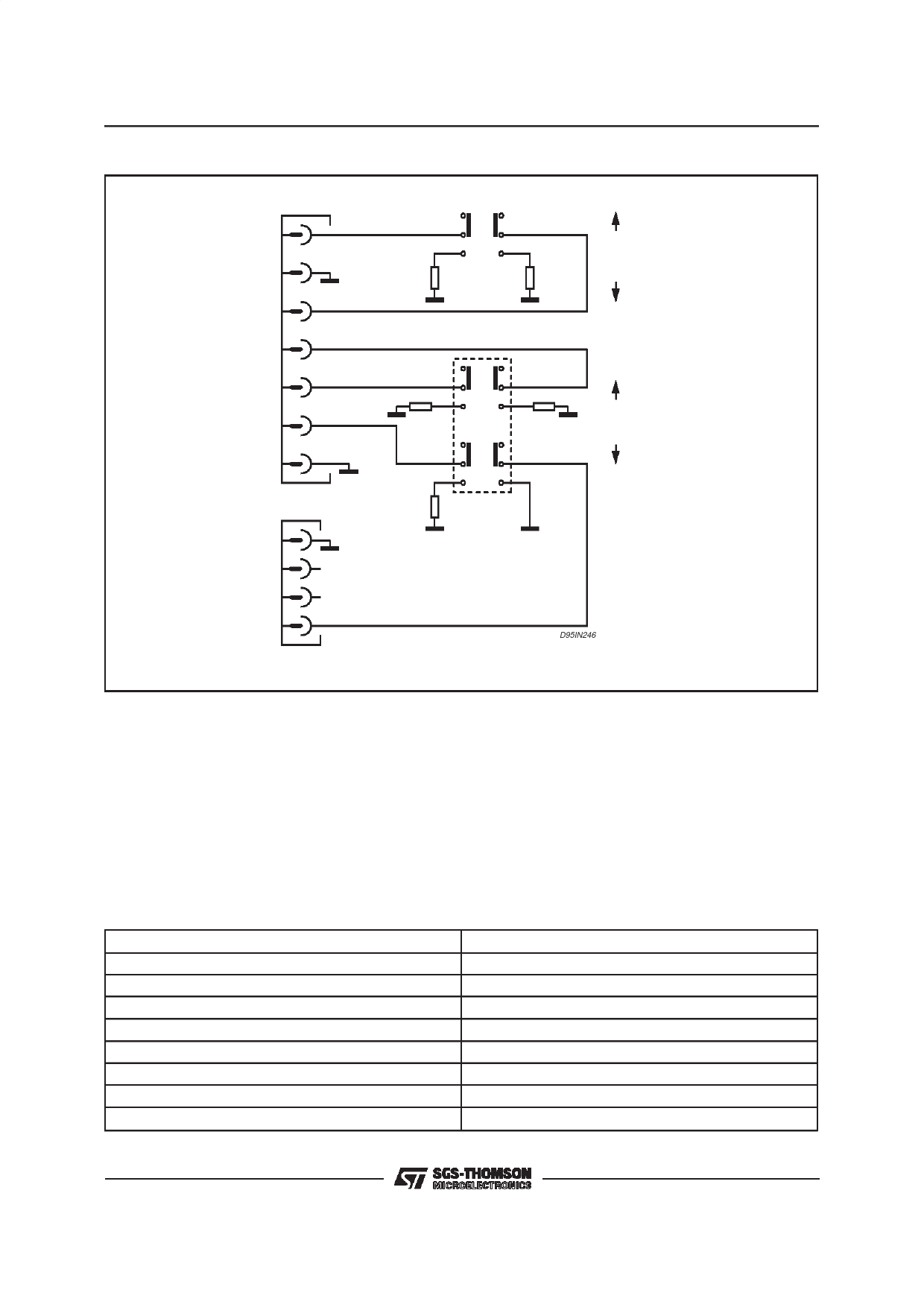
Figure 3: TVC Simulation with External Resistive Loads.
CON3
1
+14V
SOUND
OFF
2
-14V
3
10
20W
10
20W
+135V
4
+15V
5
RL 15V
+7.5V
6
SW1
RL 135V
7
ON
SBY
ON
CON2
1
2
3
S-BY
4
D95IN246
RL must be dimensioned according to the required output power
On the evaluated board (refer to CON3 in fig.3)
the adjusted voltage values are:
Voltage at out 1 = +16.5V
Voltage at out 3 = -16.5V
Voltage at out 4 = +13.7V
Voltage at out 1 = +15.7V
Voltage at out 1 = +10V
As the ” stand-by ” output values have been set,
put the switch in ON position The loads are now
connected and all the circuits of the application
run. The TEA5170 is now supplied and it sends
PWM pulses from the secondary to the primary
side of the converter. T2 is turned on, is T1 is cut-
off, thus enabling the L4981A to start. As the
PFC runs, the voltage at the bulk capacitor C23
reaches 400V.
TEST RESULTS:
Output Voltage
Output Power
Efficiency
Power Factor
THD at max. output power:
Power Factor in Stand-by Mode:
THD in Stand-by Mode:
Efficiency at min. Output Power:
Minimum Output Power = 8.5W
4/7
405V (at 230W output power).
10 to 250W
85% (at Max. output power)
0.998
3.5%
0.3
70%
0.5 (Pi min = 17W)
135V ⋅ 18mA + 15V ⋅ 300mA + 7.5V ⋅ 250mA
Share Link: 