TA7259F データシートの表示(PDF) - Toshiba
部品番号
コンポーネント説明
メーカー
TA7259F Datasheet PDF : 18 Pages
| |||
TA7259P/F/FG
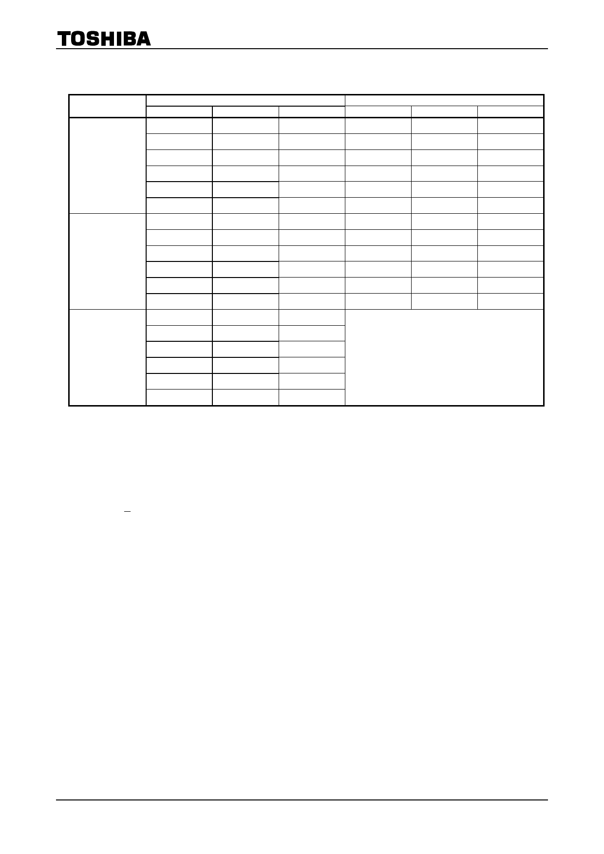
FUNCTION
FRS
(10 PIN)
L
H
M
POSITION SENSING INPUT
Ha
Hb
Hc
1
0
1
1
0
0
1
1
0
0
1
0
0
1
1
0
0
1
1
0
1
1
0
0
1
1
0
0
1
0
0
1
1
0
0
1
1
0
1
1
0
0
1
1
0
0
1
0
0
1
1
0
0
1
COIL OUTPUT
La
Lb
Lc
H
L
M
H
M
L
M
H
L
L
H
M
L
M
H
M
L
H
L
H
M
L
M
H
M
L
H
H
L
M
H
M
L
M
H
L
High Impedance
Notes)
・ Position sensing input;
“1”: Energizing +10mV or more to the positive side of each position sensing input.
“0”: Energizing −10mV or less to the negative side of each position sensing input.
In this case, DC voltage must be within the same-phase voltage range of the position sensing input.
・ Coil output;
“H”:
“M”:
V≒CCV−CC12
VSAT1
“L”: VSAT2
・ FRS input;
“L”: Applied voltage within the specified range of VF.
“H”: Applied voltage within the specified range of VR.
“M”: Applied voltage within the specified range of VS.
During testing, necessary voltage must be applied to the control input (VIN+, VIN-) and the circuit must be
driven status.
4
2006-4-14
Share Link: 