MT3170B データシートの表示(PDF) - Mitel Networks
部品番号
コンポーネント説明
メーカー
MT3170B Datasheet PDF : 11 Pages
| |||
MT3170B/71B, MT3270B/71B, MT3370B/71B
Parameter Unit Resonator Crystal
R1
Ohms
6.580
150
L1
mH
0.359
95.355
C1
pF
4.441
15.1E-03
C0
pF
34.890
12.0
Qm
-
1.299E+03 101.2E+ 03
∆f
%
±0.2%
±0.01%
Table 4. Recommended Resonator and Crystal
Specifications
Note: Qm=quality factor of RLC model, i.e., 1/2ΠƒR1C1.
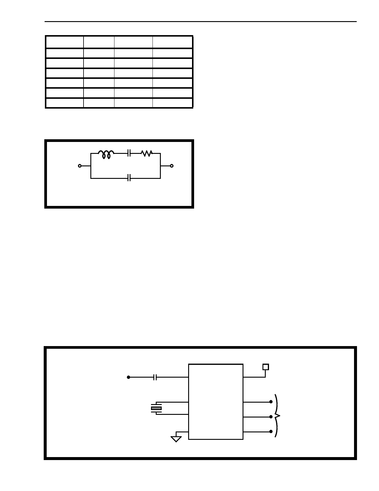
L1
C1 R1
R1 = Equivalent resistor.
C0
L1 = Equivalent inductance.
C1 = Equivalent compliance.
C0 = Capacitance between electrode.
Resonator and Crystal Electric Equivalent Circuit
Oscillator
The MT327xB/337xB can be used in both external
clock or two pin oscillator mode. In two pin oscillator
mode, the oscillator circuit is completed by
connecting either a 4.194304 MHz crystal or ceramic
resonator across OSC1 and OSC2 pins.
Specifications of the ceramic resonator and crystal
are tabulated in Table 4. It is also possible to
configure a number of these devices employing only
a single oscillator crystal. The OSC2 output of the
first device in the chain is connected to the OSC1
input of the next device. Subsequent devices are
connected similarily. The oscillator circuit can also
be driven by an 4.194304 MHz external clock applied
on pin OSC 1. The OSC2 pin should be left open.
For MT317xB devices , the CLK input is driven
directly by an 4.194304 MHz external digital clock.
Applications
The circuit shown in Figure 3 illustrates the use of a
MT327xB in a typical receiver application. It requires
only a coupling capacitor (C1) and a crystal or
ceramic resonator (X1) to complete the circuit.
The MT3x70B is designed for user who wishes to
tailor the guard time for specific applications. When
a DTMF signal is present, the ESt pin will go high.
An external microcontroller monitors ESt in real time
for a period of time set by the user. A guard time
algorithm must be implemented such that DTMF
signals not meeting the timing requirements are
rejected. The MT3x71B uses an internal counter to
provide a preset DTMF validation period. It requires
no external components. The DStD output high
indicates that a valid DTMF digit has been detected.
The 4.194304 MHz frequency has a secondary
advantage in some applications where a real time
clock is required. A 22-bit counter will count
4,194,304 cycles to provide a one second time base.
C1
DTMF/CP Input
X1
COMPONENTS LIST:
C1 = 0.1 µF ± 10 %
X1 = Crystal or Resonator (4.194304 MHz)
1 INPUT
VDD 8
MT327xB
2 OSC2
3
OSC1
7
ESt/DStD
ACK 6
4
VSS
5
SD
VDD
To microprocessor or
microcontroller
Figure 3 - Application Circuit for MT327xB
4-7
Share Link: 