LA1265 データシートの表示(PDF) - SANYO -> Panasonic
部品番号
コンポーネント説明
メーカー
LA1265 Datasheet PDF : 15 Pages
| |||
LA1265
6. If the coupling coefficient of the local OSC coil is small and an antiresonance point of approximately 100MHz is
present or the stray capacitance across pins 22 and 21 is large, a parasitic oscillation of approximately 100MHz may
occur in the buffer output (pin 22). In this case, connect a capacitance of approximately 30pF across pin 22 and GND.
7. AM OSC coil
Generally speaking, the following should be noted. Avoid winding with loose coupling between primary side and
secondary side (especially SW1, SW2). To put it concretely, the pot core type is better than the screw core type which
is loose in coupling. This prevents the local OSC frequency from turning third resonance frequency related to the
coupling coefficient.
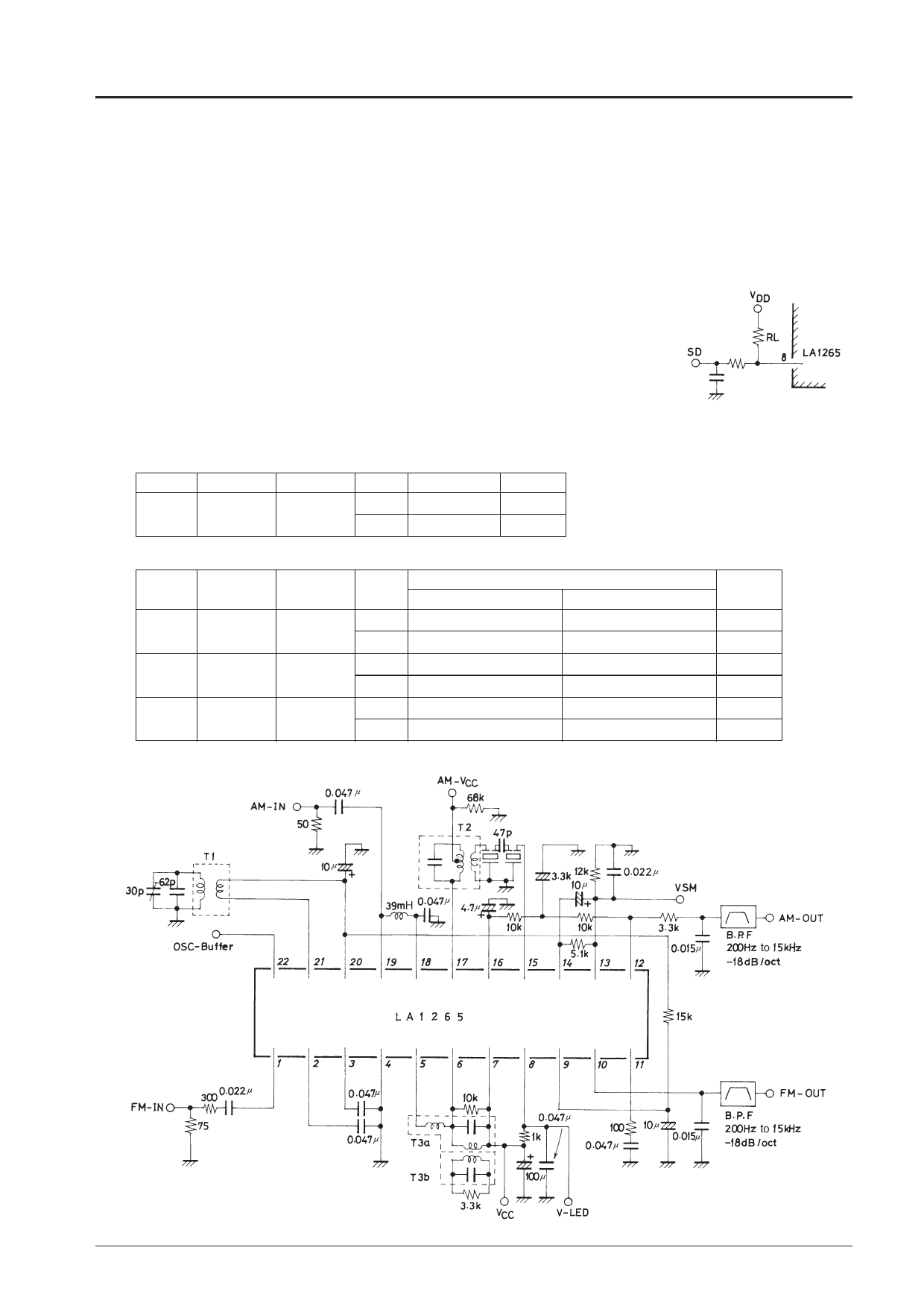
8. Resistance across pin 8 and VDD.
If pin 8 is used for the stop signal (SD) only, without using LED, it is recommended to fix
resistance RL across pin 8 and GND to be 51kΩ to 100kΩ.
9. To prevent whistle from worsening, make the pattern of AM output pin 12 as short as
possible.
Input/Output Admittance
FM
– Parameter Frequency – Admittance Unit
IF
γi1
10.7MHz ri
330
Ω
ci
20
pF
AM
–
Parameter Frequency –
Admittance
AGC-off (V16=1.4V) AGC-on (V16=2.5V)
Unit
RF
γi19
1MHz
ri
15
16
kΩ
ci
4
4
pF
MIX
γo17 500kHz ro
–
–
kΩ
co
3
3
pF
IF
γi15
500kHz ri
2
2
kΩ
co
10
8
pF
Test Circuit : FM, AM-MW
Unit (resistance : Ω, capacitance : F)
T1 4147-1457-177 (Sumida)
T2 HW-40174 (Mitsumi)
T3a HW-40130, T3b HW-40131 (Mitsumi)
No.1820-5/15
Share Link: 