ICL7106CM44_98 гғҮгғјгӮҝгӮ·гғјгғҲгҒ®иЎЁзӨәпјҲPDFпјү - Intersil
йғЁе“Ғз•ӘеҸ·
гӮігғігғқгғјгғҚгғігғҲиӘ¬жҳҺ
гғЎгғјгӮ«гғј
ICL7106CM44_98 Datasheet PDF : 16 Pages
| |||
ICL7106, ICL7107, ICL7106S, ICL7107S
Electrical Speciп¬Ғcations (Note 3) (Continued)
PARAMETER
TEST CONDITIONS
MIN TYP MAX
UNIT
DISPLAY DRIVER ICL7107 ONLY
Segment Sinking Current
(Except Pins 19 and 20)
V+ = 5V, Segment Voltage = 3V
5
8
-
mA
Pin 19 Only
10
16
-
mA
Pin 20 Only
4
7
-
mA
NOTES:
3. Dissipation rating assumes device is mounted with all leads soldered to printed circuit board.
4. Unless otherwise noted, specifications apply to both the ICL7106 and ICL7107 at TA = 25oC, fCLOCK = 48kHz. ICL7106 is tested in the
circuit of Figure 1. ICL7107 is tested in the circuit of Figure 2.
5. Back plane drive is in phase with segment drive for вҖҳoffвҖҷ segment, 180 degrees out of phase for вҖҳonвҖҷ segment. Frequency is 20 times
conversion rate. Average DC component is less than 50mV.
6. Not tested, guaranteed by design.
7. Sample Tested.
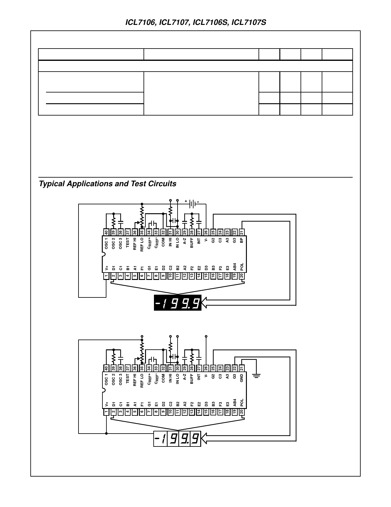
Typical Applications and Test Circuits
+ - 9V
IN
R1
R5
R3
R4
C1
C4
C5 C2 R2
C3
DISPLAY
ICL7106
DISPLAY
C1 = 0.1ВөF
C2 = 0.47ВөF
C3 = 0.22ВөF
C4 = 100pF
C5 = 0.02ВөF
R1 = 24kв„Ұ
R2 = 47kв„Ұ
R3 = 100kв„Ұ
R4 = 1kв„Ұ
R5 = 1Mв„Ұ
FIGURE 1. ICL7106 TEST CIRCUIT AND TYPICAL APPLICATION WITH LCD DISPLAY COMPONENTS SELECTED FOR 200mV
FULL SCALE
+5V
+-
-5V
IN
R1
R5
R3
R4
C1
C4
C5 C2 R2
C3
DISPLAY
ICL7107
C1 = 0.1ВөF
C2 = 0.47ВөF
C3 = 0.22ВөF
C4 = 100pF
C5 = 0.02ВөF
R1 = 24kв„Ұ
R2 = 47kв„Ұ
R3 = 100kв„Ұ
R4 = 1kв„Ұ
R5 = 1Mв„Ұ
DISPLAY
FIGURE 2. ICL7107 TEST CIRCUIT AND TYPICAL APPLICATION WITH LED DISPLAY COMPONENTS SELECTED FOR 200mV
FULL SCALE
4
Share Link: 