ASCELL3911 データシートの表示(PDF) - austriamicrosystems AG
部品番号
コンポーネント説明
メーカー
ASCELL3911 Datasheet PDF : 13 Pages
| |||
ISM 868 MHz, 433 MHz and 315 MHz FSK Transmitter – Preliminary Data Sheet
ASCell3911
Austria Mikro Systeme International AG
ASCell3911
DATA I
D_EN I
D_CLK I
WAKEUP I/O
µC_CLK I/O
µC
O SERIAL DATA OUT (P1)
O SERIAL DATA ENABLE (P2)
O SERIAL DATA CLOCK (P3)
10k
O STOP TRANSMIT (P4)
I NCLEAR
I CLK
10k
SW
Transmit
button
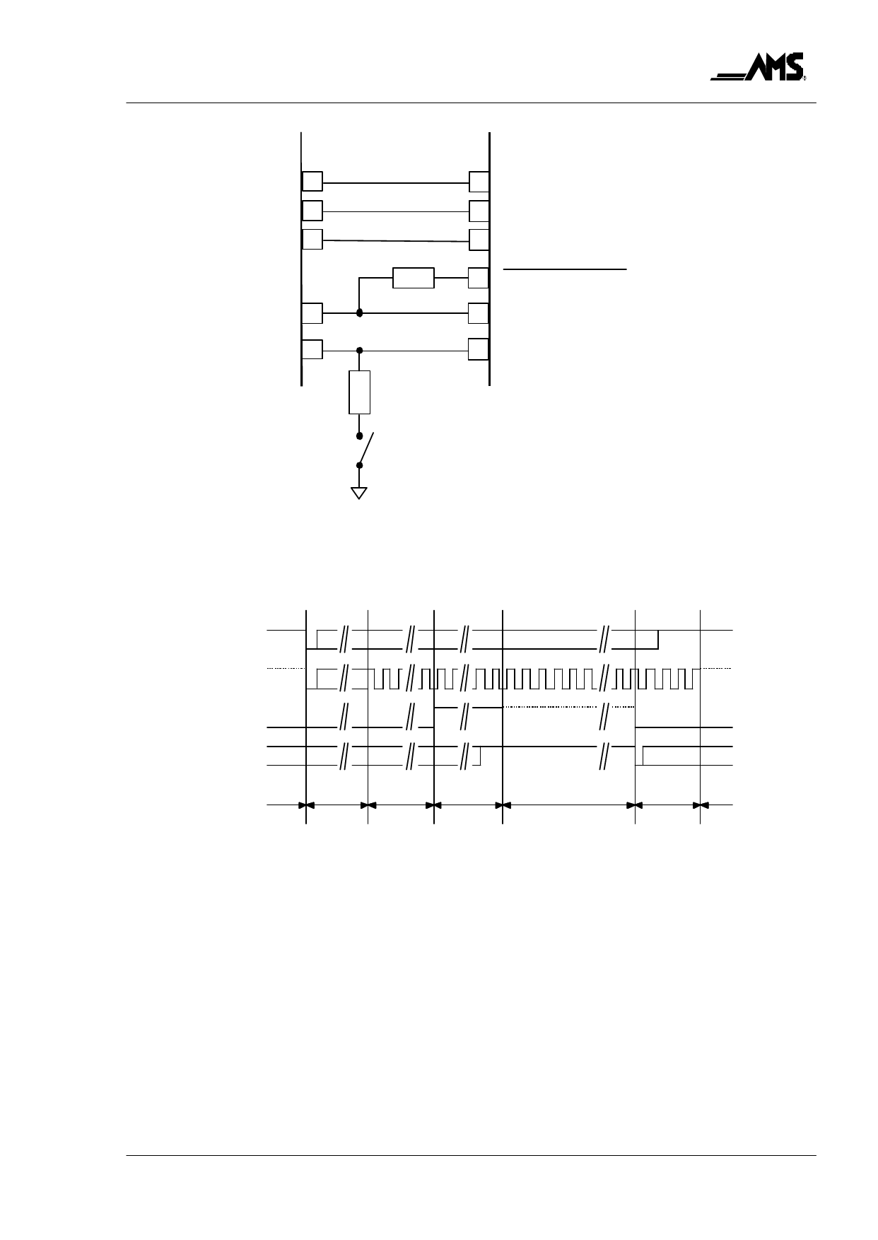
Figure 3:
Interconnection of the ASCell3911 with a typical µC with one button to wake up the whole
system (example).
Note: At room temperature, resistor values of ≈10 kΩ are suggested for the µC interface.
open
SW
closed
µC_CLK
WAKEUP
P4
standby
startup 32 clocks
SC3911 reset µC
16 clocks
startup
µC
active/transmisson
µC SC3911
4 clocks standby
power
down µC
Figure 4:
µC interface timing for wake-up and power down control.
Note:
The dashed lines indicate w eak high or low state when the µC_CLK or WAKEUP output of the ASCell3911 is disabled
(in high-resistive Z state) and pulled ”H” or ”L” by the internal pull-up device or by the µC via a resistor. These weak
states can be overridden by the ASCell3911 if the respective outputs are enabled. Whenever a line is pulled via an ex-
ternal resistor, however, this should override the internal pull-up devices of the ASCell3911.
1.6.1 Interface Description
It is assumed that the µC remains in low power standby mode as long as the P4 pin is kept ”L”
and no clock cycles are applied.
Standby: During standby (default after VCC-on) the XTAL oscillator is turned off and ASCell3911
holds the µC in a reset state:
Rev. A, February 2000
Page 6 of 13
Share Link: 