IL55 データシートの表示(PDF) - Infineon Technologies
部品番号
コンポーネント説明
メーカー
IL55 Datasheet PDF : 3 Pages
| |||
Electrical Characteristics (TA=25°C)
GaAs Emitter (per channel)
Forward Voltage
Reverse Current
Capacitance
Detector (per channel)
Collector-Emitter Breakdown Voltage
Collector-Emitter Leakage Current
Collector-Emitter Capacitance
Package
Current Transfer Ratio
IL/D/Q30/55
IL/D/Q31
Collector-Emitter Saturation Voltage
Isolation Test Voltage
Symbol
VF
IR
CO
BVCEO
ICEO
CCE
CTR
VCEsat
Min.
30/55
100
200
5300
Typ.
1.25
0.1
25
1.0
3.4
400
400
0.9
Isolation Resistance
Coupling Capacitance
Rise Time
Fall Time
RISOL
CISOL
tR
tF
1012
0.5
10
35
Max.. Unit
Condition
1.5
V
10
µA
pF
V
100
nA
pF
IF=20 mA
VR=3.0 V
VR=0 V
IC=100 µA
VCE=10 V, IF=0
VCE=10 V, f=1 MHz
%
IF=10 mA,VCE=5 V
%
IF=10 mA,VCE=5 V
1.0
V
IC=50 mA, IF=50 mA
VACRM
S
W
pF
µs
VCC=13.5 V, IF=50 mA,
µs
RL=100 Ω
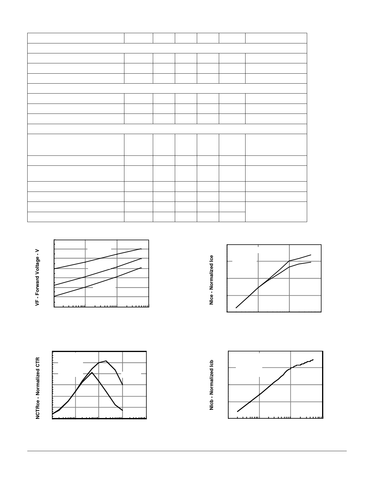
Figure 1. Forward voltage versus forward current
1.4
1.3
Ta = -55°C
1.2
1.1
Ta = 25°C
1.0
0.9
Ta = 85°C
0.8
0.7
.1
1
10
100
IF - Forward Current - mA
Figure 3. Normalized non-saturated and saturated
collector-emitter current versus LED current
10 Normalized to:
Ta = 25°C
1 IF = 10 mA
Vce = 5 V
Vce = 5 V
Vce = 1V
.1
.01
.001
.1
1
10
100
IF - LED Current - mA
Figure 2. Normalized non-saturated and saturated
CTRce at TA=25°C versus LED current
1.2 Normalized to:
1.0 Vce = 5 V
IF = 10 mA
0.8 Ta = 25 °C
Vce = 5V
0.6
0.4
0.2
0.0
.1
Vce =1V
1
10
100
IF - LED Current - mA
1000
Figure 4. Normalized collector-base photocurrent
versus LED current
10 Normalized to:
Ta = 25°C
1 Vcb = 3.5 V
IF = 10 mA
.1
.01
.001
.1
1
10
100
IF - LED Current - mA
IL/D/Q30/31/55
5–2
Share Link: 