FAN102 データシートの表示(PDF) - Fairchild Semiconductor
部品番号
コンポーネント説明
メーカー
FAN102 Datasheet PDF : 16 Pages
| |||
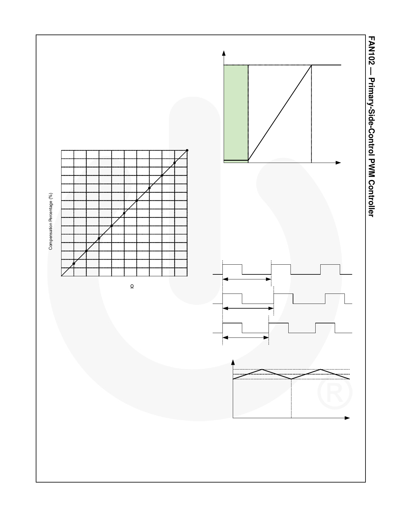
Cable Voltage Drop Compensation
When it comes to cellular phone charger applications,
the actual battery is located at the end of cable, which
causes typically several percent of voltage drop on the
actual battery voltage. FAN102 has a programmable
cable voltage drop compensation, which provides a
constant output voltage at the end of the cable over the
entire load range in CV mode. As load increases, the
voltage drop across the cable is compensated by
increasing the reference voltage of voltage regulation
error amplifier. The amount of compensation is
programmed by the resistor on the COMR pin. The
relationship between the amount of compensation and
COMR resistor is shown in Figure 26.
15
14
13
12
11
10
9
8
7
6
5
4
3
2
1
10 20 30 40 50 60 70 80 90 100
RCOMR (k )
Figure 26. Cable Voltage Drop Compensation
Temperature Compensation
Built-in temperature compensation provides constant
voltage regulation over a wide range of temperature
variation. This internal compensation current
compensates the forward-voltage drop variation of the
secondary-side rectifier diode.
Green-Mode Operation
The FAN102 uses voltage regulation error amplifier
output (VCOMV) as an indicator of the output load and
modulates the PWM frequency, as shown in Figure 27,
such that the switching frequency decreases as load
decreases. In heavy load conditions, the switching
frequency is fixed at 42KHz. Once VCOMV decreases
below 2.8V, the PWM frequency starts to linearly
decrease from 42KHz to 550Hz to reduce the switching
losses. As VCOMV decreases below 0.8V, the switching
frequency is fixed at 550Hz and FAN102 enters deep
green mode, where the operating current reduces to
1mA, further reducing the standby power consumption.
Switching Frequen cy
42kHz
Dee p
Green
Mode
Green Mode
Normal Mode
550H z
0.8V
2.8V
V COMV
Figure 27. Switching Frequency in Green Mode
Frequency Hopping
EMI reduction is accomplished by frequency hopping,
which spreads the energy over a wider frequency range
than the bandwidth measured by the EMI test
equipment. FAN102 has an internal frequency hopping
circuit that changes the switching frequency between
39.4kHz and 44.6kHz with a period of 3ms, as shown in
Figure 28.
Gate Drive Signal
ts
ts
fs
44.6kHz
42.0kHz
39.4kHz
ts
44.6kHz
3ms
t
Figure 28. Frequency Hopping
© 2008 Fairchild Semiconductor Corporation
FAN102 Rev. 1.0.3
11
www.fairchildsemi.com
Share Link: 