MAX974CSE データシートの表示(PDF) - Maxim Integrated
部品番号
コンポーネント説明
メーカー
MAX974CSE Datasheet PDF : 17 Pages
| |||
Ultra-Low-Power, Open-Drain,
Single/Dual-Supply Comparators
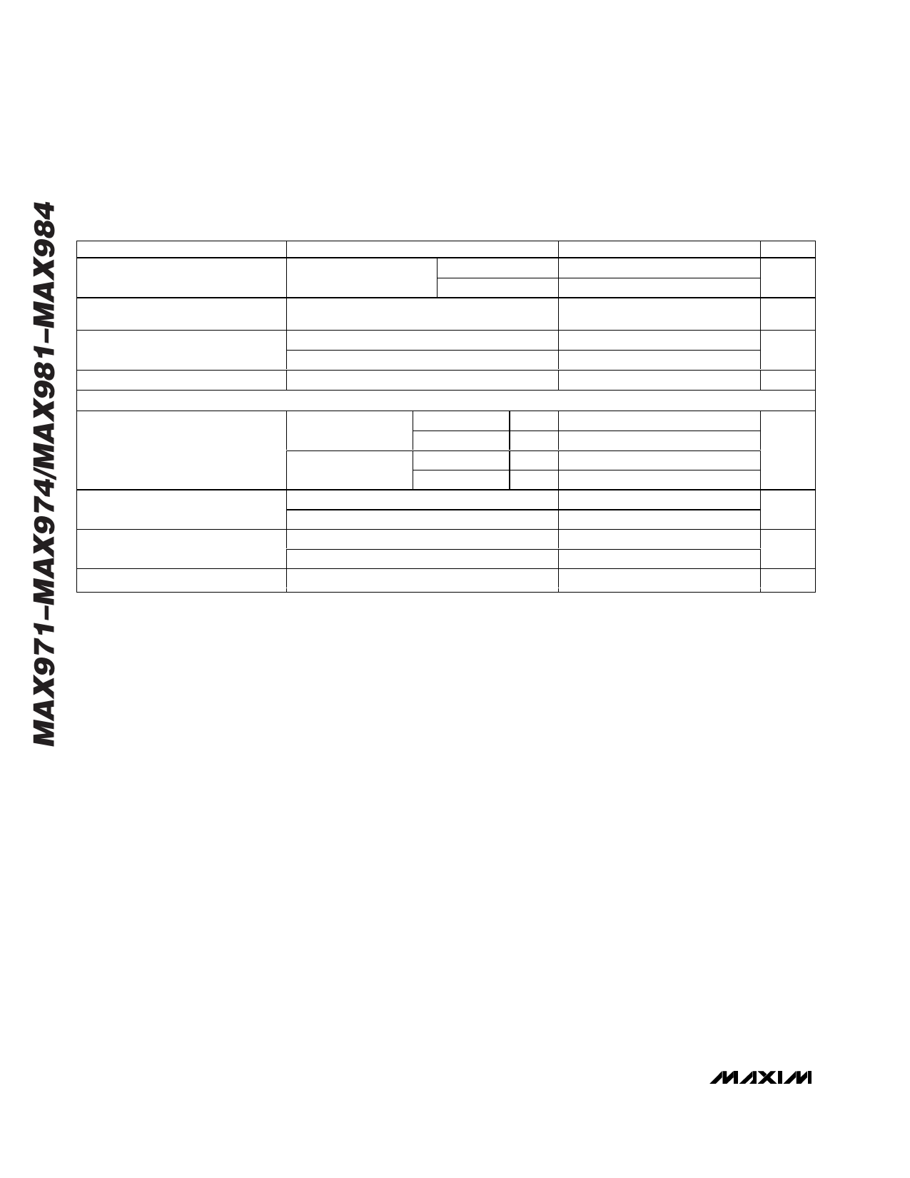
ELECTRICAL CHARACTERISTICS—3V OPERATION (continued)
(V+ = 3V, V- = GND = 0V, TA = TMIN to TMAX, unless otherwise noted. Typical values are at TA = +25°C.) (Note 1)
PARAMETER
CONDITIONS
MIN
TYP
MAX
Response Time (High-to-Low
Transition)
Response Time (Low-to-High
Transition) (Note 3)
Output Low Voltage
Output Leakage Current
TA = +25°C, 100pF load, Overdrive = 10mV
1MΩ pullup to V+
Overdrive = 100mV
TA = +25°C, 100pF load, 1MΩ pullup to V+
MAX9_2/MAX9_3, IOUT = 0.8mA
MAX9_1/MAX9_4, IOUT = 0.8mA
VOUT = 11V
12
4
300
V- + 0.4
GND + 0.4
100
REFERENCE
Reference Voltage
MAX971/MAX973/
MAX974
MAX981–MAX984
C temp range
E temp range
C temp range
E temp range
1% 1.170
2% 1.158
2% 1.158
3% 1.147
1.182
1.182
1.194
1.206
1.206
1.217
Source Current
TA = +25°C
C/E temp ranges
15
25
6
Sink Current
TA = +25°C
C/E temp ranges
8
15
4
Voltage Noise
100Hz to 100kHz
100
UNITS
µs
µs
V
nA
V
µA
µA
µVRMS
Note 1: The MAX972EBL is 100% tested at TA = +25°C. Temperature limits are guaranteed by design.
Note 2: MAX974/MAX984 comparators work below 2.5V; see Low-Voltage Operation section for more details.
Note 3: Low-to-high response time is the result of the 1MΩ pullup and the 100pF capacitive load, based on three time constants.
A faster response time is achieved with a smaller RC.
4 _______________________________________________________________________________________
Share Link: 