P4SMA12A_14 データシートの表示(PDF) - Littelfuse, Inc
部品番号
コンポーネント説明
メーカー
P4SMA12A_14 Datasheet PDF : 6 Pages
| |||
TVS Diodes
Surface Mount – 400W > P4SMA series
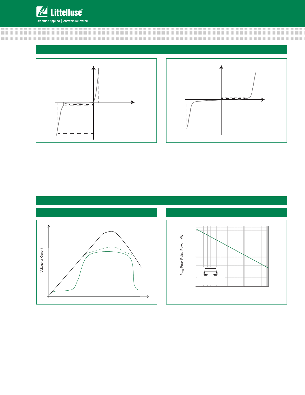
I-V Curve Characteristics
Uni-directional
Bi-directional
Ipp
Vc VBR VR
IR VF
V
IT
Vc VBR VR
IT
IR
IR
IT
V
VR VBR Vc
Ipp
Ipp
P Peak Pulse Power Dissipation -- Max power dissipation
PPM
VR Stand-off Voltage -- Maximum voltage that can be applied to the TVS without operation
V Breakdown Voltage -- Maximum voltage that flows though the TVS at a specified test current (I )
BR
T
VC Clamping Voltage -- Peak voltage measured across the suppressor at a specified Ippm (peak impulse current)
IR Reverse Leakage Current -- Current measured at VR
VF Forward Voltage Drop for Uni-directional
Ratings and Characteristic Curves (TA=25°C unless otherwise noted)
Figure 1 - TVS Transients Clamping Waveform
Figure 2 - Peak Pulse Power Rating Curve
Voltage Transients
10
Voltage Across TVS
Current Through TVS
1
Time
0.2x0.2" (5.0x5.0mm)
Copper Pad Area
0.1
0.000001
0.00001
0.0001
td-Pulse Width (sec.)
0.001
continues on next page.
P4SMA Series
28
©2014 Littelfuse, Inc.
Specifications are subject to change without notice.
Revised: 10/09/14
Share Link: 