SB5100 データシートの表示(PDF) - SUNMATE electronic Co., LTD
部品番号
コンポーネント説明
メーカー
SB5100 Datasheet PDF : 2 Pages
| |||
SB520 – SB5100
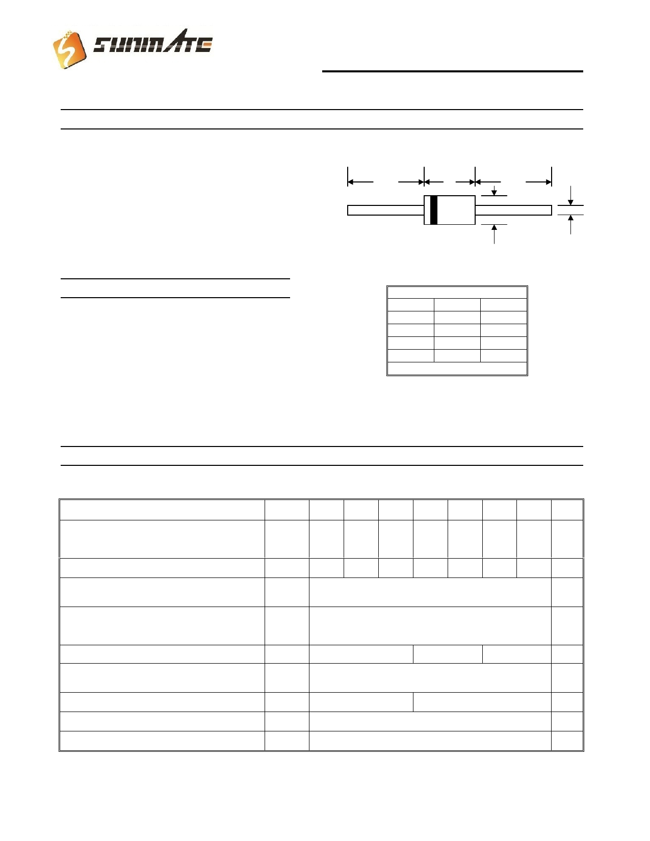
5.0A Axial Leaded Schottky Barrier Diode
Features
! Schottky Barrier Chip
! Guard Ring Die Construction for
Transient Protection
! High Current Capability
! Low Power Loss, High Efficiency
! High Surge Current Capability
! For Use in Low Voltage, High Frequency
A
B
A
Inverters, Free Wheeling, and Polarity
Protection Applications
C
D
Mechanical Data
! Case: DO-201AD, Molded Plastic
! Terminals: Plated Leads Solderable per
MIL-STD-202, Method 208
! Polarity: Cathode Band
! Weight: 1.2 grams (approx.)
! Mounting Position: Any
! Marking: Type Number
! Lead Free: For RoHS / Lead Free Version,
Add “-LF” Suffix to Part Number, See Page 4
DO-201AD
Dim
Min
Max
A
25.4
—
B
7.20
9.50
C
1.20
1.30
D
4.80
5.30
All Dimensions in mm
Maximum Ratings and Electrical Characteristics @TA=25°C unless otherwise specified
Single Phase, half wave, 60Hz, resistive or inductive load.
For capacitive load, derate current by 20%.
Characteristic
Symbol SB520 SB530 SB540 SB550 SB560 SB580 SB5100 Unit
Peak Repetitive Reverse Voltage
Working Peak Reverse Voltage
DC Blocking Voltage
VRRM
VRWM
20
30
40
50
60
80
100
V
VR
RMS Reverse Voltage
VR(RMS)
14
21
28
35
42
56
70
V
Average Rectified Output Current @TL = 100°C
(Note 1)
IO
5.0
A
Non-Repetitive Peak Forward Surge Current 8.3ms
Single half sine-wave superimposed on rated load
IFSM
150
A
(JEDEC Method)
Forward Voltage
@IF = 5.0A
VFM
Peak Reverse Current
At Rated DC Blocking Voltage
@TA = 25°C
@TA = 100°C
IRM
Typical Junction Capacitance (Note 2)
Cj
0.55
0.70
0.85
V
0.5
50
mA
500
400
pF
Typical Thermal Resistance (Note 1)
RJA
10
°C/W
Operating and Storage Temperature Range
Tj, TSTG
-65 to +150
°C
Note: 1. Valid provided that leads are kept at ambient temperature at a distance of 9.5mm from the case.
2. Measured at 1.0 MHz and applied reverse voltage of 4.0V D.C.
1of2
Share Link: 