2SD1270Q(2003) データシートの表示(PDF) - Panasonic Corporation
部品番号
コンポーネント説明
メーカー
2SD1270Q Datasheet PDF : 4 Pages
| |||
Power Transistors
2SD1270
Silicon NPN epitaxial planar type
For power switching
Complementary to 2SB0945
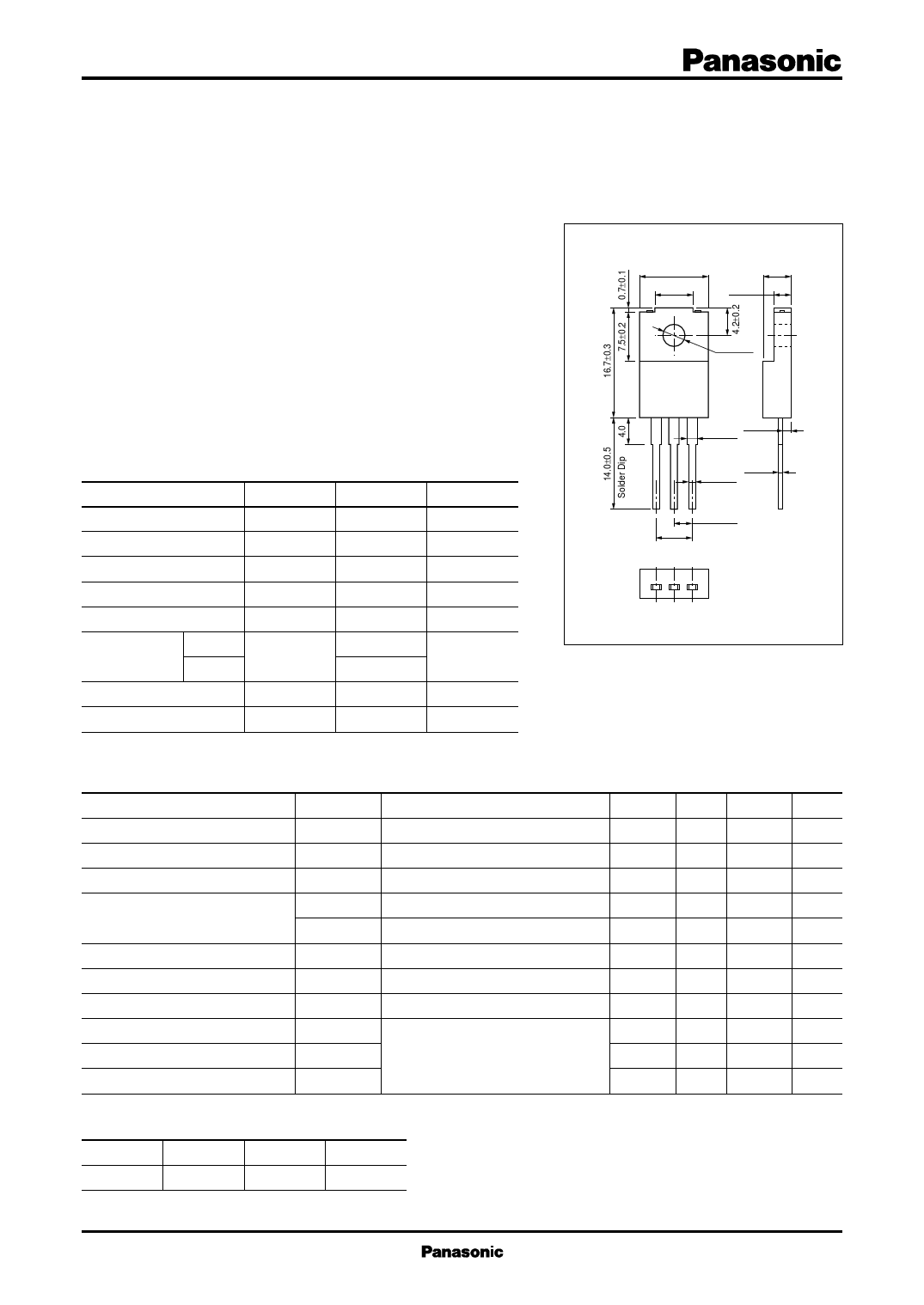
10.0±0.2
5.5±0.2
Unit: mm
4.2±0.2
2.7±0.2
■ Features
• Low collector-emitter saturation voltage VCE(sat)
φ 3.1±0.1
• Satisfactory linearity of forward current transfer ratio hFE
• Large collector current IC
• Full-pack package which can be installed to the heat sink with one screw.
1.4±0.1
1.3±0.2
/ ■ Absolute Maximum Ratings TC = 25°C
0.8±0.1
0.5+–00..12
e Parameter
Symbol Rating
Unit
pe) Collector-base voltage (Emitter open) VCBO
130
V
nc d ge. ed ty Collector-emitter voltage (Base open) VCEO
80
V
sta tinu Emitter-base voltage (Collector open) VEBO
7
V
a e cycle iscon Collector current
IC
5
A
life d, d Peak collector current
ICP
10
A
n u duct type Collector power
PC
40
W
te tin Pro ued dissipation
Ta = 25°C
2.0
four ntin Junction temperature
Tj
150
°C
ing isco Storage temperature
Tstg −55 to +150 °C
2.54±0.3
5.08±0.5
1: Base
123
2: Collector
3: Emitter
EIAJ: SC-67
TO-220F-A1 Package
ain onludes foell,opwlaned d ■ Electrical Characteristics TC = 25°C ± 3°C
inc typ Parameter
Symbol
Conditions
c tinued ance Collector-emitter voltage (Base open)
M is con inten Collector-base cutoff current (Emitter open)
/Dis ma Emitter-base cutoff current (Collector open)
D ance type, Forward current transfer ratio
ainten nance Collector-emitter saturation voltage
M ainte Base-emitter saturation voltage
d m Transition frequency
(plane Turn-on time
VCEO
ICBO
IEBO
hFE1
hFE2 *
VCE(sat)
VBE(sat)
fT
ton
IC = 10 mA, IB = 0
VCB = 100 V, IE = 0
VEB = 5 V, IC = 0
VCE = 2 V, IC = 0.1 A
VCE = 2 V, IC = 2 A
IC = 4 A, IB = 0.2 A
IC = 4 A, IB = 0.2 A
VCE = 10 V, IC = 0.5 A, f = 10 MHz
IC = 2 A, IB1 = 0.2 A, IB2 = − 0.2 A
Min Typ Max Unit
80
V
10
µA
50
µA
45
60
260
0.5
V
1.5
V
30
MHz
0.5
µs
Storage time
tstg
VCC = 50 V
1.5
µs
Fall time
tf
0.15
µs
Note) 1. Measuring methods are based on JAPANESE INDUSTRIAL STANDARD JIS C 7030 measuring methods for transistors.
2. *: Rank classification
Rank
R
Q
P
hFE2
60 to 120
90 to 180 130 to 260
Publication date: February 2003
SJD00184BED
1
Share Link: 