S7010 データシートの表示(PDF) - Hamamatsu Photonics
部品番号
コンポーネント説明
メーカー
S7010 Datasheet PDF : 10 Pages
| |||
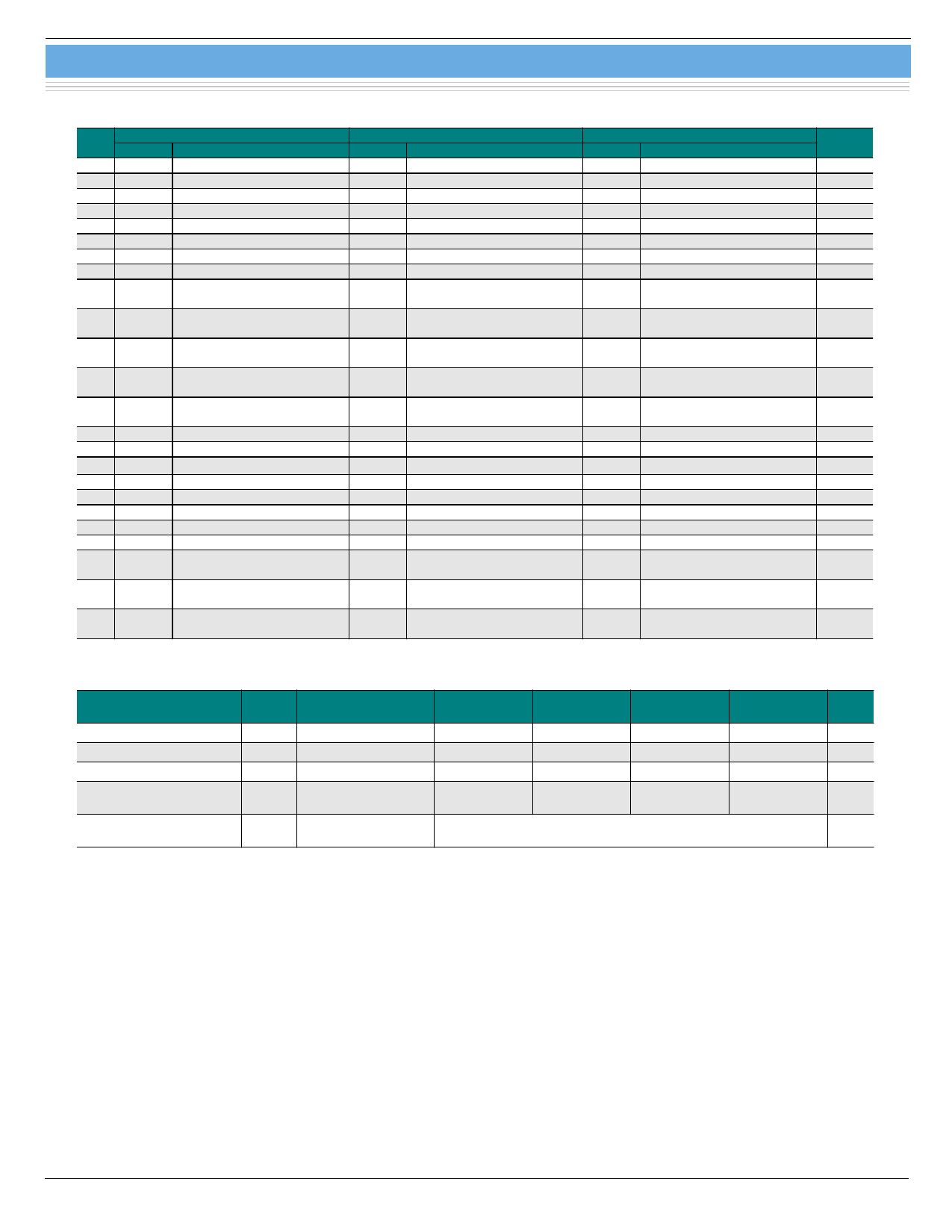
CCD area image sensor S7010/S7011/S7015 series
I Pin connections
Pin
No. Symbol
S7010 series
Description
Symbol
S7011 series
Description
Symbol
S7015 series
Description
Remark
1
RG Reset gate
RG Reset gate
RG Reset gate
2
RD Reset drain
RD Reset drain
RD Reset drain
3
OS Output transistor source
OS Output transistor source
OS Output transistor source
4
OD Output transistor drain
OD Output transistor drain
OD Output transistor drain
5
OG Output gate
OG Output gate
OG Output gate
6
SG Summing gate
SG Summing gate
SG Summing gate
=P2H
7
NC
Th1 Thermistor
Th1 Thermistor
8
NC
Th2 Thermistor
Th2 Thermistor
9
P2H
CCD horizontal register
clock-2
P2H
CCD horizontal register
clock-2
P2H
CCD horizontal register
clock-2
10
P1H
CCD horizontal register
clock-1
P1H
CCD horizontal register
clock-1
P1H
CCD horizontal register
clock-1
11
IG2H
Test point
(horizontal input gate-2)
IG2H
Test point
(horizontal input gate-2)
IG2H
Test point
(horizontal input gate-2)
0V
12
IG1H
Test point
(horizontal input gate-1)
IG1H
Test point
(horizontal input gate-1)
IG1H
Test point
(horizontal input gate-1)
0V
13
ISH
Test point
(horizontal input source)
ISH
Test point
(horizontal input source)
ISH
Test point
(horizontal input source)
=RD
14 P2V CCD vertical register clock-2 P2V CCD vertical register clock-2 P2V CCD vertical register clock-2
15 P1V CCD vertical register clock-1 P1V CCD vertical register clock-1 P1V CCD vertical register clock-1
16 TG *18 Transfer gate
TG *18 Transfer gate
TG *18 Transfer gate
=P2V
17 NC
NC
NC
18 NC
P- TE-cooler-
P- TE-cooler-
19 NC
P+ TE-cooler+
P+ TE-cooler+
20 SS Substrate (GND)
SS Substrate (GND)
SS Substrate (GND)
21 NC
NC
NC
22
ISV
Test point
(vertical input source)
ISV
Test point
(vertical input source)
ISV
Test point
(vertical input source)
=RD
23
IG2V
Test point
(vertical input gate-2)
IG2V
Test point
(vertical input gate-2)
IG2V
Test point
(vertical input gate-2)
0V
24
IG1V
Test point
(vertical input gate-1)
IG1V
Test point
(vertical input gate-1)
IG1V
Test point
(vertical input gate-1)
0V
*18 TG: Isolation gate between vertical register and horizontal register. In standard operation, TG should be applied the same pulse as P2V.
I Specifications of built-in TE-cooler (Typ.)
Parameter
Symbol
Condition
S7011-0906/
-0907
S7011-1006/
-1007
S7015-0908
S7015-1008
Unit
Internal resistance
Rint Ta=25 °C
2.8
6.0
2.5
1.2
W
Maximum current *19
Imax Tc *20=Th *21=25 °C
1.5
1.5
1.5
3.0
A
Maximum voltage
Vmax Tc *20=Th *21=25 °C
4.4
8.8
3.8
3.6
V
Maximum heat
absorption *22
Qmax
3.4
6.7
3.4
5.1
W
Maximum temperature
of heat radiating side
-
70
°C
*19: Maximum current Imax:
If the current greater than this value flows into the thermoelectric cooler, the heat absorption begins to decrease due to the
Joule heat. It should be noted that this value is not the damage threshold value. To protect the thermoelectric cooler and
maintain stable operation, the supply current should be less than 60 % of this maximum current.
*20: Temperature of the cooling side of thermoelectric cooler.
*21: Temperature of the heat radiating side of thermoelectric cooler.
*22: Maximum heat absorption Qmax.
This is a heat absorption when the maximum current is supplied to the TE-cooler.
8
Share Link: 