SG1842L データシートの表示(PDF) - Microsemi Corporation
部品番号
コンポーネント説明
メーカー
SG1842L Datasheet PDF : 24 Pages
| |||
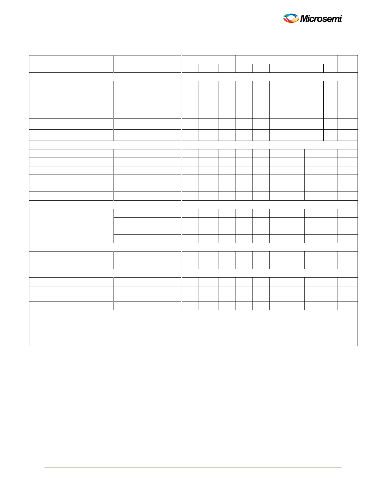
Electrical Characteristics (continued)
Electrical Characteristics (continued)
Symbol
Parameter
Test Conditions
Current Sense Section
CSAVOL Gain 2, 3
Maximum Input Signal2 VCOMP = 5V
PSRR
Power
Ratio2
Supply
Rejection
12V
≤
VCC
≤
25V
SG1842/43
SG2842/43
SG3842/43
Units
Min Typ Max Min Typ Max Min Typ Max
2.85 3 3.15 2.85 3 3.15 2.85 3 3.15 V/V
0.9 1 1.1 0.9 1 1.1 0.9 1 1.1 V
70
70
70
dB
CSIB Input Bias Current
-2 -10
-2 -10
-2 -10 µA
CSDELAY Delay to Output1
150 300
150 300
150 300 ns
Output Section
VOL Output Low Level
ISINK = 20mA
ISINK = 200mA
VOH Output High Level
ISOURCE = 20mA
ISOURCE = 200mA
RS
Rise Time
TJ = 25°C, CL = 1nF
FT
Fall Time
TJ = 25°C, CL = 1nF
Under-Voltage Lockout Section
0.1 0.4
0.1 0.4
0.1 0.4 V
1.5 2.2
1.5 2.2
1.5 2.2 V
13 13.5
13 13.5
13 13.5
V
12 13.5
12 13.5
12 13.5
V
50 150
50 150
50 150 ns
50 150
50 150
50 150 ns
UVLO Start Threshold
1842/2842/3842
1843/2843/3843
15 16 17 15 16 17 14.5 16 17.5 V
7.8 8.4 9.0 7.8 8.4 9.0 7.8 8.4 9.0 V
VSMIN
Min. Operation Voltage 1842/2842/3842
After Turn-On
1843/2843/3843
9 10 11 9 10 11 8.5 10 11.5 V
7.0 7.6 8.3 7.0 7.6 8.2 7.0 7.6 8.2 V
PWM Section
DCMAX Maximum Duty Cycle
93 95 100 90 95 100 90 95 100 %
DCMIN Minimum Duty Cycle
0
0
0%
Power Consumption Section
IS
Start-Up Current
I
Operating Supply
Current
VFB = VISENSE = 0V
0.5 1
11 17
0.5 1
11 17
0.5 1 mA
11 17 mA
Z
VCC Zener Voltage
ICC = 25mA
34
34
34
V
Notes:
1. These parameters, although guaranteed, are not 100% tested in production.
2. Parameter measured at trip point of latch with VVFB = 0.
3. Gain defined as: A = ∆VCOMP / ∆VISENSE ; 0 ≤ VISENSE ≤ 0.8V
4. Adjust VCC above the start threshold before setting at 15V.
7
Share Link: 