ADM690AAN データシートの表示(PDF) - Analog Devices
部品番号
コンポーネント説明
メーカー
ADM690AAN Datasheet PDF : 8 Pages
| |||
ADM690A/ADM692A/ADM802L/M/ADM805L/M
ABSOLUTE MAXIMUM RATINGS*
(TA = +25°C unless otherwise noted)
VCC . . . . . . . . . . . . . . . . . . . . . . . . . . . . . . . . . –0.3 V to +6 V
VBATT . . . . . . . . . . . . . . . . . . . . . . . . . . . . . . . –0.3 V to +6 V
All Other Inputs . . . . . . . . . . . . . . . . . . –0.3 V to VCC + 0.3 V
Input Current
VCC . . . . . . . . . . . . . . . . . . . . . . . . . . . . . . . . . . . . .200 mA
VBATT . . . . . . . . . . . . . . . . . . . . . . . . . . . . . . . . . . . 50 mA
GND . . . . . . . . . . . . . . . . . . . . . . . . . . . . . . . . . . . . 20 mA
Digital Output Current . . . . . . . . . . . . . . . . . . . . . . . . 20 mA
Power Dissipation, N-8 DIP . . . . . . . . . . . . . . . . . . . 400 mW
θJA Thermal Impedance . . . . . . . . . . . . . . . . . . . . 120°C/W
Power Dissipation, SO-8 SOIC . . . . . . . . . . . . . . . . . 500 mW
θJA Thermal Impedance . . . . . . . . . . . . . . . . . . . . 110°C/W
Operating Temperature Range
Industrial (A Version) . . . . . . . . . . . . . . . . –40°C to +85°C
Lead Temperature (Soldering, 10 sec) . . . . . . . . . . . . +300°C
Vapor Phase (60 sec) . . . . . . . . . . . . . . . . . . . . . . . . +215°C
Infrared (15 sec) . . . . . . . . . . . . . . . . . . . . . . . . . . . .+220°C
Storage Temperature Range . . . . . . . . . . . . –65°C to +150°C
ESD Rating . . . . . . . . . . . . . . . . . . . . . . . . . . . . . . . . . . >4 kV
*Stresses above those listed under “Absolute Maximum Ratings” may cause
permanent damage to the device. This is a stress rating only and functional
operation of the device at these or any other conditions above those listed in the
operational sections of this specification is not implied. Exposure to absolute
maximum ratings for extended periods of time may affect device reliability.
Model
ADM690AAN
ADM690AARN
ADM690AARM
ADM692AAN
ADM692AARN
ADM802LAN
ADM802LARN
ADM802MAN
ADM802MARN
ADM805LAN
ADM805LARN
ADM805MAN
ADM805MARN
ORDERING GUIDE
Temperature
Range
–40°C to +85°C
–40°C to +85°C
–40°C to +85°C
–40°C to +85°C
–40°C to +85°C
–40°C to +85°C
–40°C to +85°C
–40°C to +85°C
–40°C to +85°C
–40°C to +85°C
–40°C to +85°C
–40°C to +85°C
–40°C to +85°C
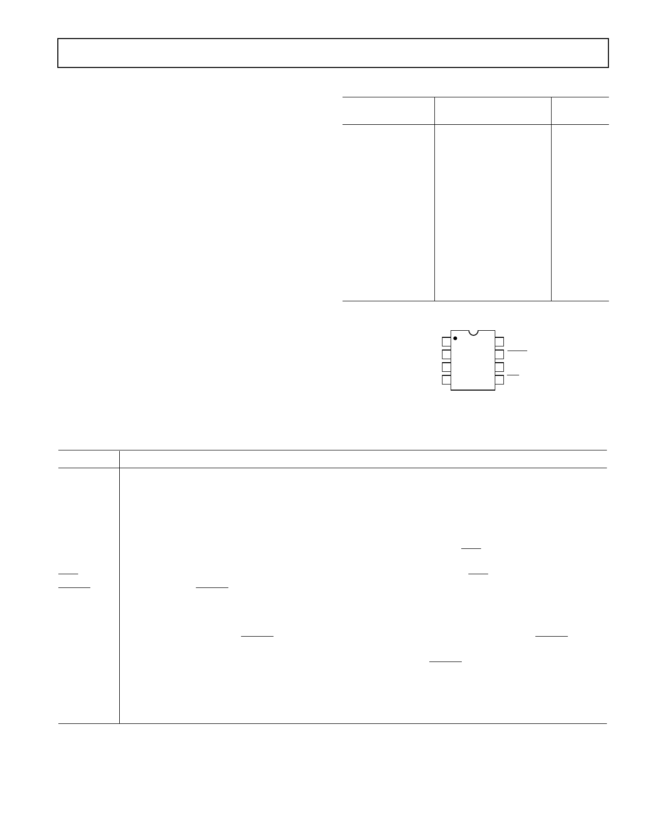
PIN CONFIGURATIONS
VOUT 1
VCC 2
GND 3
PFI 4
ADM690A
ADM692A
ADM802L
ADM802M
ADM805L
ADM805M
TOP VIEW
(Not to Scale)
8 VBATT
7 RESET (RESET)
6 WDI
5 PFO
Package
Option
N-8
SO-8
RM-8
N-8
SO-8
N-8
SO-8
N-8
SO-8
N-8
SO-8
N-8
SO-8
Mnemonic
VCC
VBATT
VOUT
GND
PFI
PFO
RESET
RESET
WDI
PIN FUNCTION DESCRIPTION
Function
Power Supply Input: +5 V Nominal.
Backup Battery Input. As VCC falls below the reset threshold and below VBATT by 20 mV, VBATT will be switched
to VOUT. On power-up as VCC rises to 20 mV above VBATT, VOUT will be switched back to VCC.
Output Voltage. When VCC is above the reset threshold, VOUT is connected to VCC through an on chip switch.
When VCC is below the reset threshold, the higher of VCC or VBATT is connected to VOUT.
0 V. Ground reference for all signals.
Power Fail Comparator Input. If PFI is less than 1.25 V, the power fail output PFO goes low. If unused, PFI
should be connected to VCC or GND.
Power Fail Comparator Output. If PFI is less than 1.25 V, the power fail output PFO goes low.
Logic Output. RESET goes low if
1. VCC falls below the Reset Threshold
2. The watchdog timer is not serviced within its timeout period (1.6 seconds)
The reset threshold is typically 4.65 V for the ADM690A/ADM802L/ADM805L and 4.4 V for the ADM692A/
ADM802M/ADM805M. RESET remains low for 200 ms after VCC returns above the threshold. RESET also
goes low for 200 ms if the watchdog timer is enabled but not serviced within its timeout period.
Active high RESET output (ADM805L/M only). This is the inverse of RESET. The asserted (high) level is VCC
or VBATT whichever is higher.
Watchdog Input. WDI is a three level input. If WDI remains either high or low for longer than 1.6 s, (RESET)
(RESET) is activated. The timer resets with each transition on the WDI line. The watchdog timer may be
disabled if WDI is left floating or is connected to a high impedance three stated logic output.
REV. 0
–3–
Share Link: 