24C02S „Éá„Éľ„āŅ„ā∑„Éľ„Éą„ĀģŤ°®Á§ļÔľąPDFÔľČ - Unspecified
ťÉ®ŚďĀÁē™ŚŹ∑
„ā≥„É≥„ÉĚ„Éľ„Éć„É≥„ÉąŤ™¨śėé
„É°„Éľ„āę„Éľ
24C02S Datasheet PDF : 8 Pages
| |||
Turbo IC, Inc.
24C01/24C02
PRODUCT INTRODUCTION
DESCRIPTION (Continued):
For a write operation, the master issues a start condition, a
device address byte, a memory address byte, and then up to
8 data bytes. The Turbo IC 24C01/24C02 acknowledges
after each byte transmission. To terminate the transmission,
the master issues a stop condition by pulling SDA from low
to high while SCL is high.
DEVICE OPERATION:
For a read operation, the master issues a start condition and
a device address byte. The Turbo IC 24C01/24C02 acknowl-
edges, and then transmits a data byte, which is accessed
from the EEPROM memory. The master acknowledges, indi-
cating that it requires more data bytes. The Turbo IC 24C01/
24C02 transmits more data bytes, with the memory address
counter automatically incrementing for each data byte, until
the master does not acknowledge, indicating that it is termi-
nating the transmission. The master then issues a stop con-
dition.
BIDIRECTIONAL BUS PROTOCOL:
The Turbo IC 24C01/24C02 follows the I²C bus protocol. The
protocol defines any device that sends data onto the SDA
bus as a transmitter, and the receiving device as a receiver.
The device controlling the transfer is the master and the de-
vice being controlled is the slave. The master always initiates
the data transfers, and provides the clock for both transmit
and receive operations. The Turbo IC 24C01/24C02 acts as
a slave device in all applications. Either the master or the
slave can take control of the SDA bus, depending on the
requirement of the protocol.
ACKNOWLEDGE:
All data is serially transmitted in bytes (8 bits) on the SDA
bus. The acknowledge protocol is used as a handshake sig-
nal to indicate successful transmission of a byte of data. The
bus transmitter, either the master or the slave (Turbo IC
24C01/24C02), releases the bus after sending a byte of data
on the SDA bus. The receiver pulls the SDA bus low during
the ninth clock cycle to acknowledge the successful trans-
mission of a byte of data. If the SDA is not pulled low during
the ninth clock cycle, the Turbo IC 24C01/24C02 terminates
the data transmission and goes into standby mode.
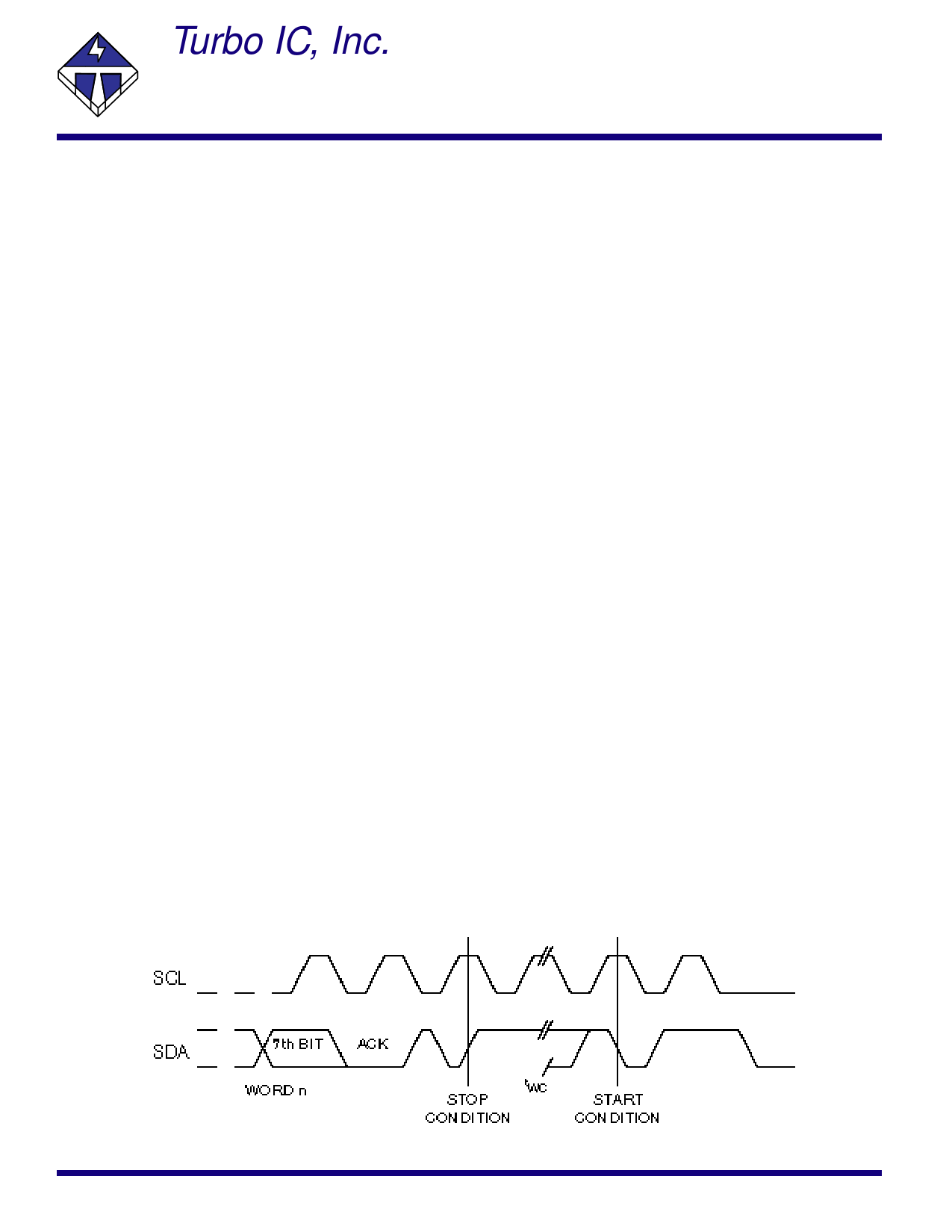
START/STOP CONDITION AND DATA TRANSITIONS:
While SCL clock is high, a high to low transition on the SDA
bus is recognized as a START condition which precedes any
read or write operation. While SCL clock is high, a low to
high transition on the SDA bus is recognized as a STOP con-
dition which terminates the communication and places the
Turbo IC 24C01/24C02 into standby mode. All other data
transitions on the SDA bus must occur while SCL clock is
low to ensure proper operation.
For the write operation, the Turbo IC 24C01/24C02 acknowl-
edges after the device address byte, acknowledges after the
memory address byte, and acknowledges after each subse-
quent data byte.
For the read operation, the Turbo IC 24C01/24C02 acknowl-
edges after the device address byte. Then the Turbo IC 24C01/
24C02 transmits each subsequent data byte, and the mas-
ter acknowledges after each data byte transfer, indicating
that it requires more data bytes. The Turbo IC 24C01/24C02
monitors the SDA bus for the acknowledge. To terminate the
transmission, the master does not acknowledge, and then
sends a stop condition.
Write Cycle Timing
Note: The write cycle time tWC is the time from a valid stop condition of a write sequence to the end of the internal clear / write cycle.
2
Share Link: 